122
C
ABLING INTERFACES
CHAPTER 4 INSTALLATION
Cable Requirements
Terminal interfaces
The number of available terminal interfaces on the mainboard can be increased by fitting interface cards.
The RJ45 connector assignment is the same for interfaces of the mainboard and terminal cards.
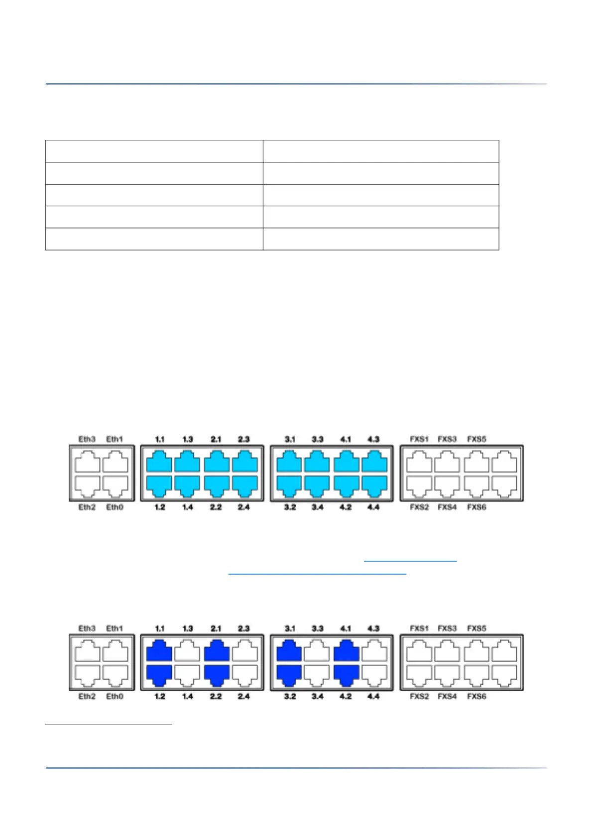
DSI terminal interfaces
With interface cards EADP4 and the appropriate wiring adapters, DSI terminal interfaces can be made
available at the RJ45 sockets 1.x...4.x. The possible RJ45 sockets are highlighted in colour in the figure
below.
Figure 4.29: Connection possibilities for DSI terminal interfaces on single assigned RJ45
sockets
With interface cards 8DSI
1
and the appropriate wiring adapters, DSI terminal interfaces can be made
available at the multiply assigned RJ45 sockets x.1 and x.2. The signals can be split again to individual
RJ45 sockets using patch cables and the fan-out panel FOP (see Fan-out panel FOP
, ) or with 8-fold
assigned connecting cables (see e.g. Prefabricated system cable 4 x RJ45
).The possible RJ45 sockets
are highlighted in colour in the figure below.
Figure 4.30: Connection possibilities for DSI terminal interfaces on multiply assigned RJ45
sockets
Table 4.18:Cable requirements for FXO network interface
Core pairs X cores 1 X 2
Stranded not required
Wire diameter, core 0.4 … 0.8 mm
Screening not required
Resistance max. 2 X 250 W
1. Not yet supported with Release 6.0