196
D
ISPLAY AND CONTROL PANEL
CHAPTER 6 OPERATION AND MAINTENANCE
LED display
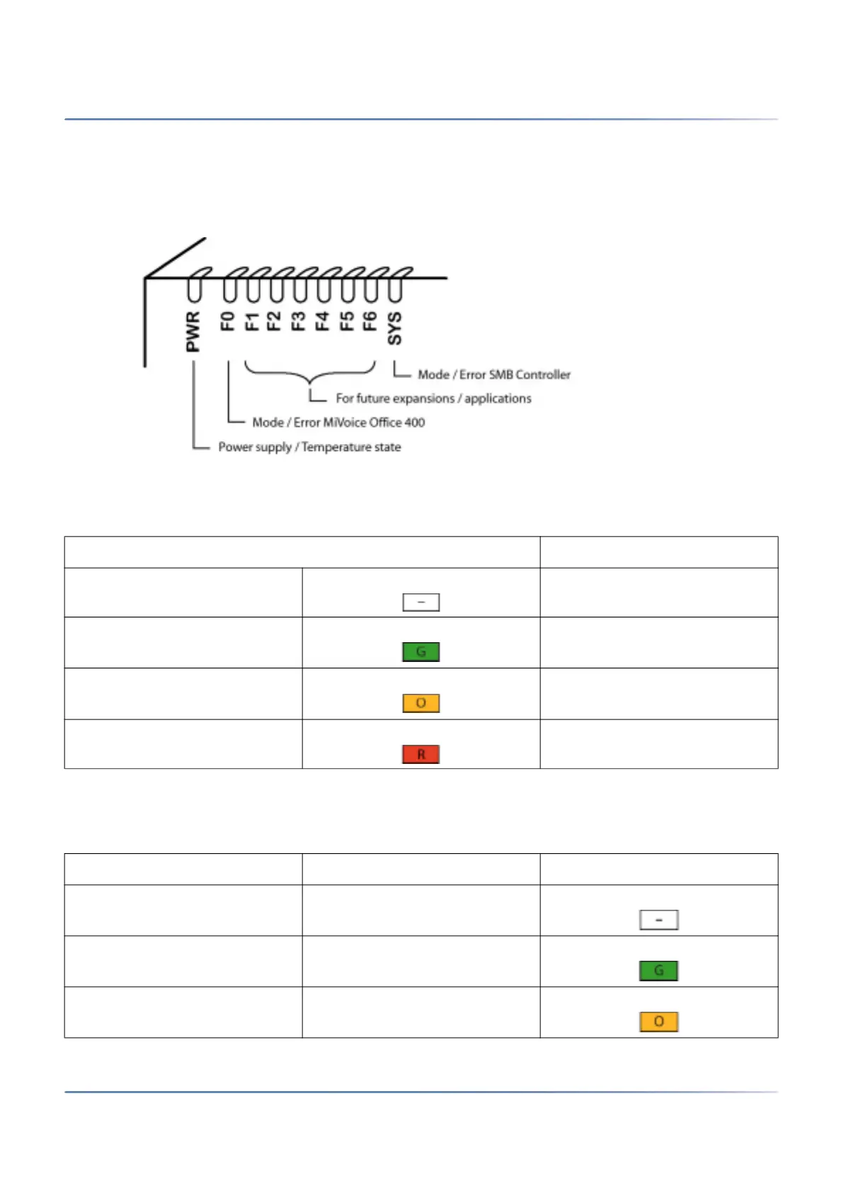
The front panel contains an LED display field with a total of 9 labelled LEDs. It is used as an operating
state and error indicator during the start-up phase and during operation.
Figure 6.4: LED display
Each LED can take on one of four states: green (G), orange (O), red (R) and inactive. In general the
colours have the following meaning:
The following display patterns and symbols have been defined for displaying an mode or an error of the
SMB Controller or a running application (e.g. MiVoice Office 400):
Table 6.3:Significance of the LEDs colours
Colour Meaning
Inactive Switched off
Green Normal operation / everything
in order
Orange Function is being carried out / is
active
Red Warning / error
Table 6.4:Defined display patterns (Sheet 1 of 2)
LED activation period Description Symbol
Always off Inactive
Always on Steady green
Always on Steady orange