42
B
ASIC SYSTEM
CHAPTER 3 EXPANSION STAGES AND SYSTEM CAPACITY
• CPU module on mainboard, fitted with a RAM module
• Fitted fan
• Power supply unit with power cord
Interfaces, display and control elements
The following mainboard interfaces can be accessed only when the housing cover of the communication
server is open:
The following interfaces, display and control elements of the mainboard are routed to the front panel:
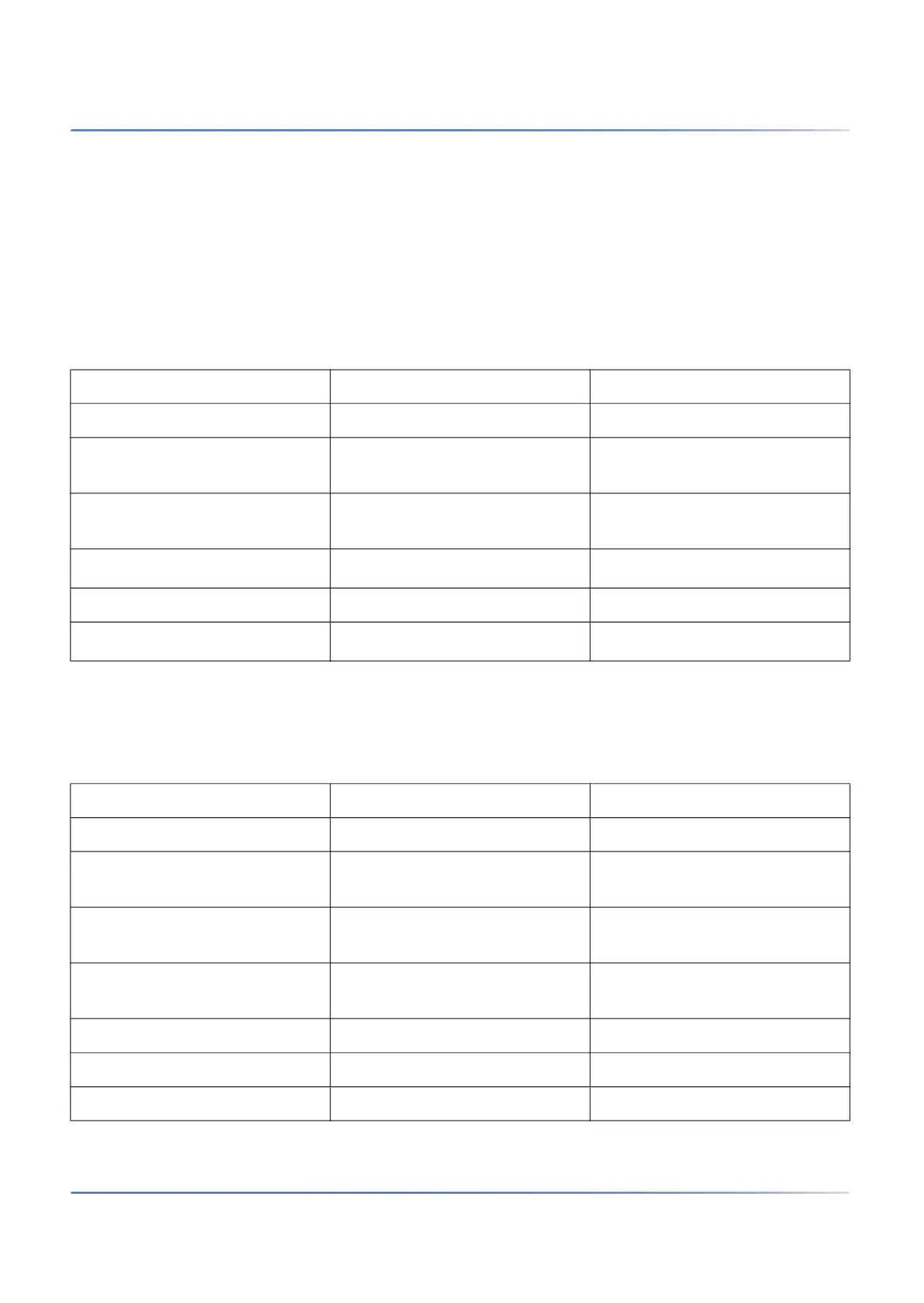
Table 3.1:Mainboard
Interfaces SMBC Designation / Remarks
Slots for interface cards 4 IC1...IC4 / with snap mechanism
Slots for DSP modules 1 DSP1...3 / three DSP modules,
stackable
Slots for wiring adapters 4 WA1...WA4 / one slot per wiring
adapter
Slot for IP media module
1
1. Not supported
1 1 module
Slot for CPU module 1 CPU / 1 module (already fitted)
Fan interface
2
2. The fan is always required
1 FAN / 3-pin connector
Table 3.2:Front panel
Interfaces SMBC Note
FXS terminal interfaces 6 RJ45 socket (FXS1...FXS6)
Ethernet interfaces 1Gbit/s
(LAN)
4
1
RJ45 socket (Eth0...Eth3)
RJ45 sockets on front panel for
interface cards
16 RJ45 socket (x.1...x.4)
RJ45 sockets on front panel, not
usable
2 RJ45 socket, not wired
Supply input 1 2-pin supply socket
Pilot key 1
LED display 1