140
C
ABLING INTERFACES
CHAPTER 4 INSTALLATION
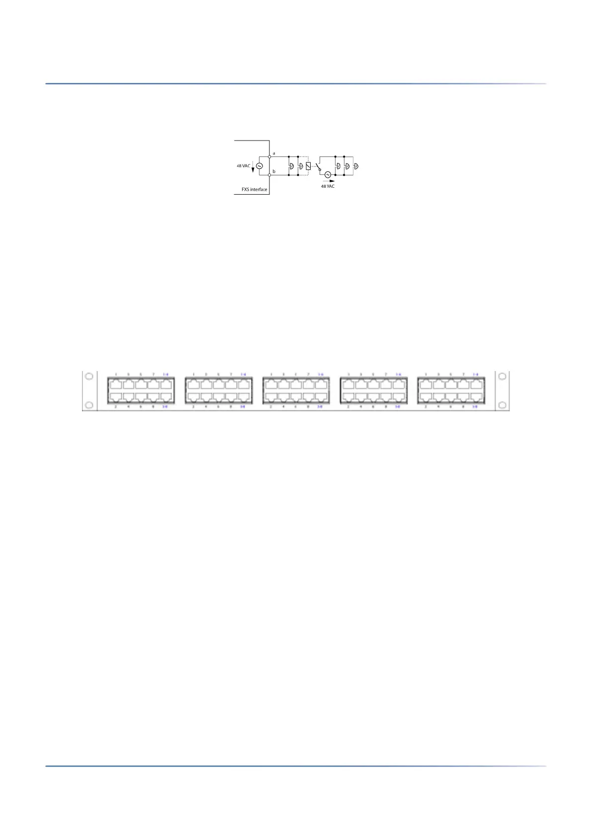
several devices connected in parallel) must not fall below 1 kW. The ringing voltage is 48 VAC. A 48 V
relay must be interposed when connecting a large number of auxiliary bells.
Figure 4.49: Connection for FXS mode: General bell
See also
"General bell on FXS interface" in the "System Functions and Features" System Manual.
Fan-out panel FOP
The interface cards 8DSI have four-fold assigned RJ45 sockets. With the fan-out panel FOP a total of 10
four-fold assigned RJ45 sockets can be split to individual RJ45 sockets.
The fan-out panel (FOP) takes up the space of one height unit in a rack and can be fitted directly above
or below the communication server.
Figure 4.50: Front panel, FOP fan-out-panel
Fan-out panels can also be offset, e.g. as floor distributors.
NOTE: The fan-out panel FOP must be installed in a 19” rack.
Connection
The diagram below shows the connection of an interface card 8DSI on slot IC1 with terminals. With this
card and the appropriate wiring adapter 2 four-fold assigned RJ45 sockets are available on the front panel
on interface 1.1 and 1.2 while the 2 remaining RJ45 sockets 1.3 and 1.4 are not used. The 2 four-fold
assigned sockets are looped via the front panel of the fan-out-panel connector (FOP) strip using 2 patch
cables.