139
C
ABLING INTERFACES
CHAPTER 4 INSTALLATION
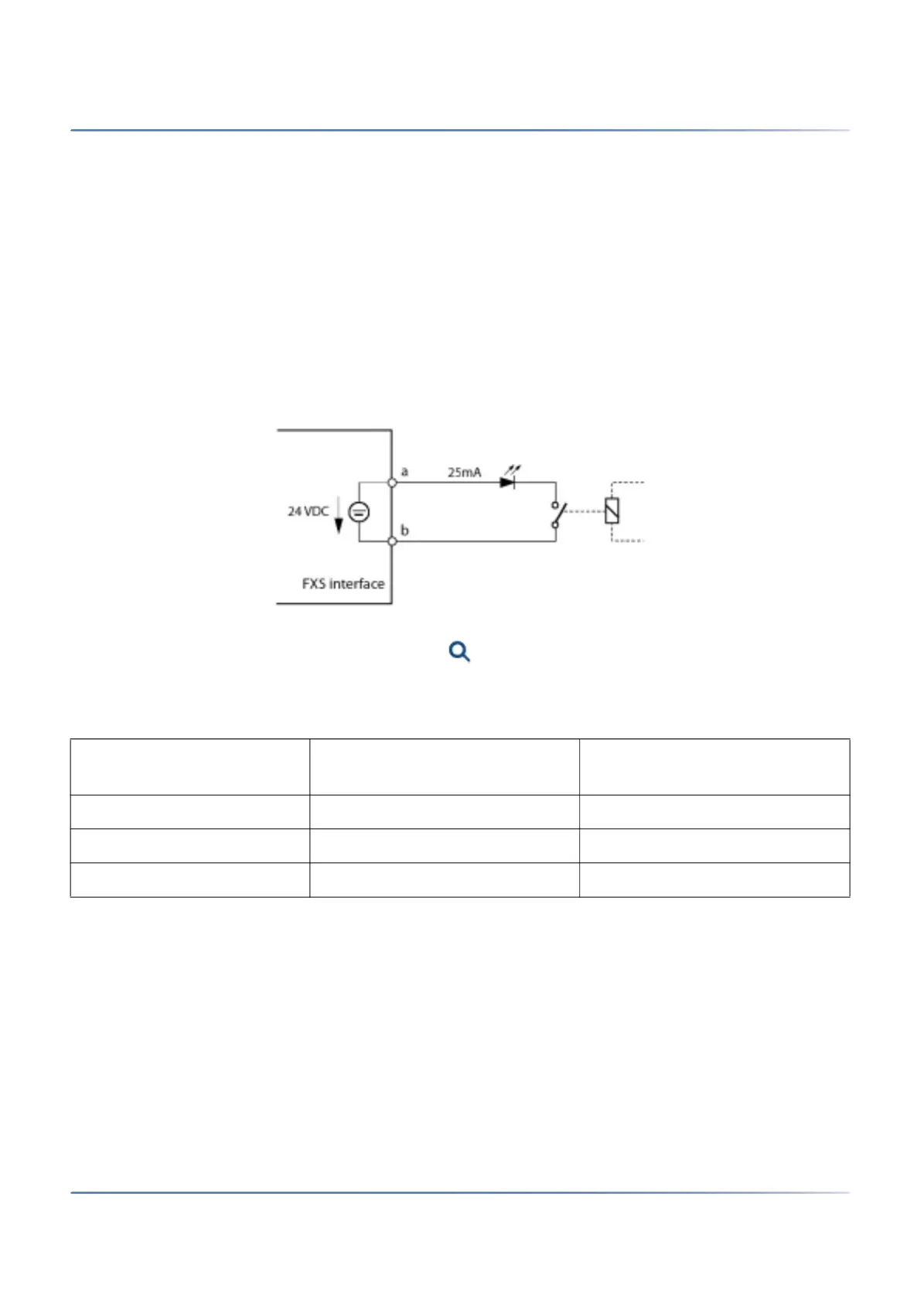
FXS mode: Control input
If FXS interfaces are configured as control inputs, one or more of the switch groups can be switched
between Positions 1, 2 and 3. An external switch or a relay is connected for this purpose. An LED can be
connected to the circuit to indicate the switch state. The no-load voltage is 24 VDC; the current is limited
to 25mA.
The permissible switch and loop resistances are as follows:
• Active state (On): lt; 1 kW
• Passive state (Off): > 4 kW
There are no special requirements for the cables.
CAUTION: Control inputs must have a floating connection.
Figure 4.48: Connection for FXS mode: Control input
In the switch group configuration in ( =xb) the ports are assigned to the control inputs of a switch group.
To be able to control all 3 switch positions of a switch group, you need 2 control inputs which switch the
switch position of the switch group depending on the status.
Other conditions:
• The same control inputs can control one or more switch groups.
• The same switch group can only be switched by the 2 assigned control inputs.
• Control of the switch groups using the control inputs takes priority over control using function codes.
FXS mode: General bell
One FXS interface per communication server can be configured for the connection of a general bell. It is
possible to use commercial auxiliary bells designed for connection in parallel to analogue terminals as a
general bell. However the impedance of the connected general bell (or total impedance in the case of
Table 4.32:Switch group control via the control inputs
FXS control input 1 FXS control input 2 Switch positions of the switch
group
Off Off Position 1
On Off Position 2
any On Position 3