43
B
ASIC SYSTEM
CHAPTER 3 EXPANSION STAGES AND SYSTEM CAPACITY
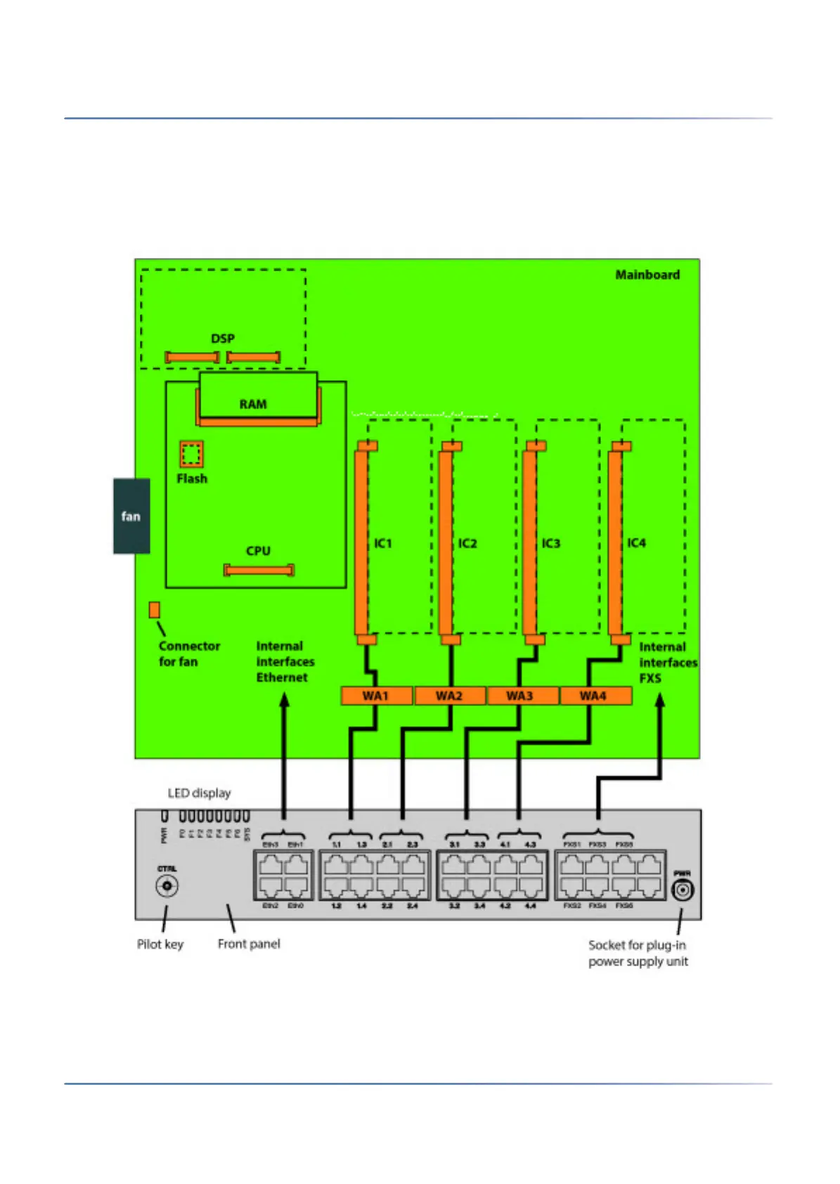
The diagram below shows the position of all the interfaces and slots on the mainboard display and control
elements and on the front panel.
Figure 3.2: Mainboard interfaces, display and control elements and front panel
Legend:
IC1...4 Slots for interface cards (trunk cards and terminal cards)
1. Only 1 interface (eth0) is usable for MiVoice Office 400