125
Function assignment of external
terminal and control
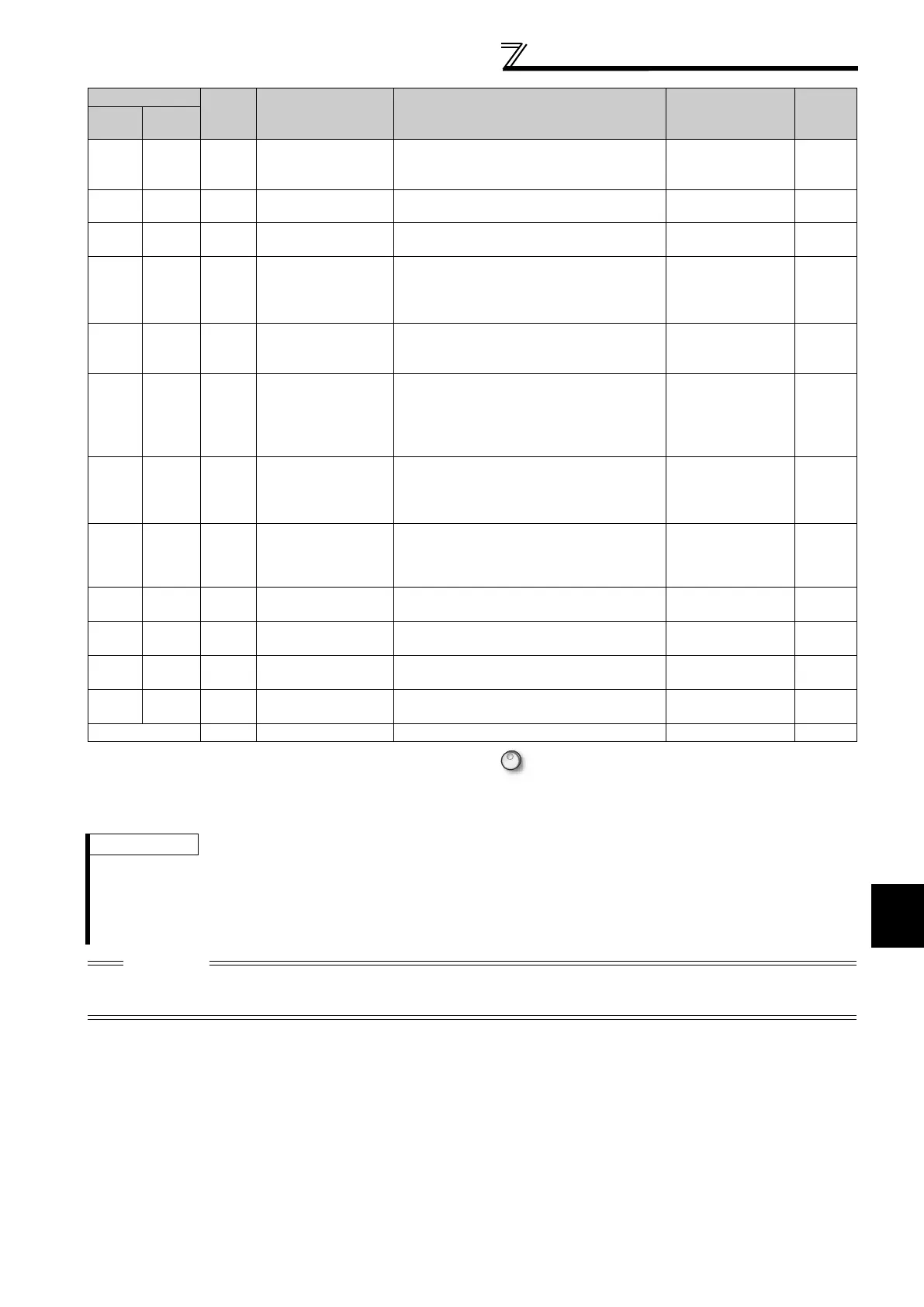
79 179 Y79
Pulse train output of
output power
Output in pulses every time the accumulated
output power of the inverter reaches the
Pr.799 setting.
Pr. 799
133
82 182 Y82 BACnet binary output
Control of binary output from BACnet is
available.
242
85 185 Y85 DC feeding
Output during power failure or under voltage
of AC power.
Pr. 30, Pr. 70 108
90 190 Y90 Life alarm
Output when any of the control circuit
capacitor, main circuit capacitor and inrush
current limit circuit or the cooling fan
approaches the end of its service life.
Pr. 255 to Pr. 259 297
91 191 Y91
Fault output 3
(power-OFF signal)
Output when a fault occurs due to the
internal circuit failure of inverter wiring
mistake.
127
92 192 Y92
Energy saving
average value
updated timing
Turned ON and OFF alternately every time
the power saving average value is updated
when the power saving monitor is used.
Cannot be set to Pr. 195 and Pr. 196 (relay
output terminal).
Pr. 52, Pr. 54,
Pr. 158, Pr. 891 to
Pr. 899
159
93 193 Y93
Current average
value monitor signal
Average current value and maintenance
timer value are output as pulses.
Cannot be set to Pr. 195 and Pr. 196 (relay
output terminal).
Pr. 555 to Pr. 557 301
94 194 ALM2 Fault output 2
Output when the fault occurs. Continues
outputting the signal during inverter reset
and stops outputting after reset is cancelled.
*2
126
95 195 Y95
Maintenance timer
signal
Output when Pr. 503 rises to or above the Pr.
504 setting.
Pr. 503, Pr. 504 300
96 196 REM Remote output
Output to the terminal when a value is set to
the parameter.
Pr. 495 to Pr. 497
132
98 198 LF Alarm output
Output when an alarm (fan failure or
communication error warning) occurs.
Pr. 121, Pr. 244
209,
296
99 199 ALM Fault output
Output when the fault occurs. The signal
output is stopped when the fault is reset.
126
9999 No function
*1 Note that when the frequency setting is varied using an analog signal or of the operation panel (FR-DU07), the output of the SU (up to
frequency) signal may alternate ON and OFF depending on that varying speed and the timing of the varying speed due to acceleration/
deceleration time setting. (The output will not alternate ON and OFF when the acceleration/deceleration time setting is "0s".)
*2 When a power supply reset is performed, the fault output 2 signal (ALM2) turns OFF as soon as the power supply switches OFF.
REMARKS
The same function may be set to more than one terminal.
When the function is executed, the terminal conducts at the setting of any of "0" to "99", and does not conduct at the setting of
any of "100" to "199".
When Pr. 76 Fault code output selection = "1", the output signals of the terminals SU, IPF, OL and FU are switched as set in Pr. 76.
(When an inverter fault occurs, the signal output is switched to the fault code output.)
The output assignment of the terminal RUN and fault output relay are as set above regardless of Pr. 76.
CAUTION
Changing the terminal assignment using Pr. 190 to Pr. 196 (output terminal function selection) may affect the other functions.
Please set parameters after confirming the function of each terminal.
Do not assign signals which repeat frequent ON/OFF to A1 B1 C1, A2 B2 C2. Otherwise, the life of the relay contact decreases.
Setting
Signal
Name
Function Operation
Related
Parameters
Refer
to Page
Positive
Logic
Negative
Logic

 Loading...


