192
Selection of operation mode and
operation location
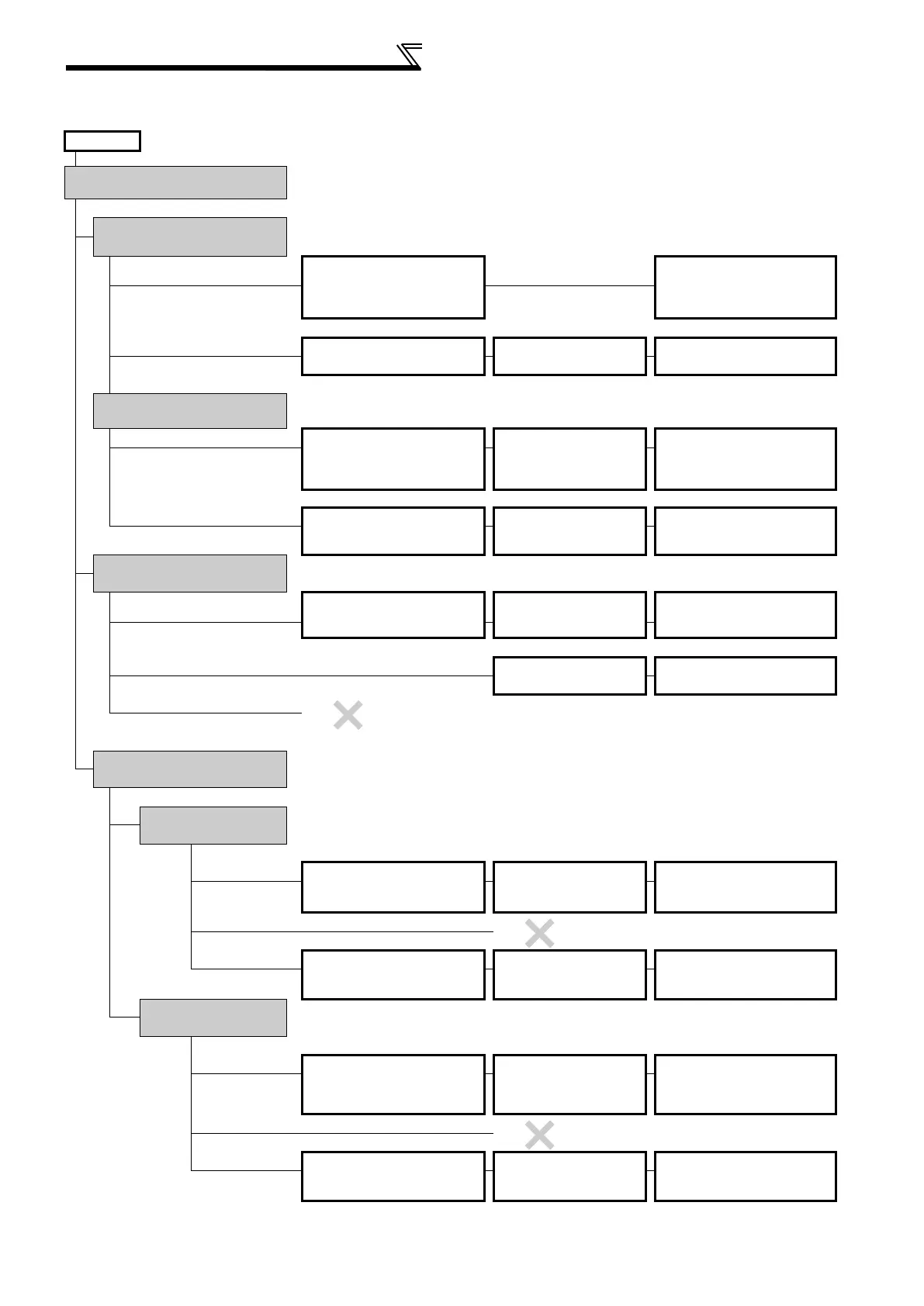
(3) Operation mode selection flow
In the following flowchart, select the basic parameter setting and terminal connection related to the operation mode.
START
Connection Parameter setting Operation
Where is the start command
source?
From external
(STF/STR terminal)
Where is the frequency set?
From external
(Terminal 2, 4,
JOG, multi-speed, etc.)
STF (forward rotation)/STR
(reverse rotation)
(Refer to page 117.)
Terminal 2, 4 and 5 (analog), RL,
RM, RH, JOG, etc.
Frequency setting terminal ON
STF(STR) ON
From PU (Digital setting)
STF (forward rotation)/STR
(reverse rotation)
(Refer to page 117.)
Pr. 79 = "3"
(External/PU combined
operation 1)
DU digital setting
STF(STR) ON
From communication (RS-485 terminals/communication option)
RS-485 terminals or
communication option?
RS-485 terminals
STF (forward rotation)/STR
(reverse rotation)
(Refer to page 117.)
Connection of RS-485 terminals
(Refer to page 206.)
Pr. 338 = "1"
Pr. 340 = "1, 2"
Communication frequency setting
command sending
STF(STR) ON
Communication option
Connection of communication
option
(Refer to the corresponding communication
option instruction manual)
Pr. 338 = "1"
Pr. 340 = "1"
Communication frequency setting
command sending
STF(STR) ON
From PU (FWD/REV key)
Where is the frequency set?
From external
(Terminal 2, 4, JOG,
multi-speed, etc.)
Terminal 2, 4 and 5 (analog), RL,
RM, RH, JOG, etc.
Pr. 79 = "4"
(External/PU combined
operation 2)
Frequency setting terminal ON
FWD/REV key ON
From PU (Digital setting)
Pr. 79 = "1"
(Fixed to PU operation)
Digital setting
FWD/REV key ON
From communication
(RS-485 terminals/communication option)
From communication (RS-485 terminals/communication option)
RS-485 terminals or
communication option?
RS-485 terminals
Where is the frequency
set
?
From external
(Terminal 2, 4, JOG, multi-speed, etc.)
Connection of RS-485 terminals
(Refer to page 206.)
Terminal 2, 4 and 5 (analog), RL,
RM, RH, JOG, etc.
Pr. 339 = "1"
Pr. 340 = "1, 2"
Frequency setting terminal ON
Communication start command
sending
From PU (Digital setting)
From communication
RS-485 terminals
Connection of RS-485 terminals
(Refer to page 206.)
Pr. 340 = "1, 2"
Communication frequency setting
command sending
Communication start command
sending
Communication option
Where is the frequency
set?
From
external
(Terminal 2, 4, JOG, multi-speed, etc.)
Connection of communication option
(Refer to the corresponding communication
option instruction manual)
Terminal 2, 4 and 5 (analog), RL,
RM, RH, JOG, etc.
Pr. 339 = "1"
Pr. 340 = "1"
Frequency setting terminal ON
Communication start command
sending
From PU (Digital setting)
From communication (
communication option)
Connection of communication option
(Refer to the corresponding communication
option instruction manual)
Pr. 340 = "1"
Communication frequency setting
command sending
Communication start command
sending

 Loading...


