193
Selection of operation mode and
operation location
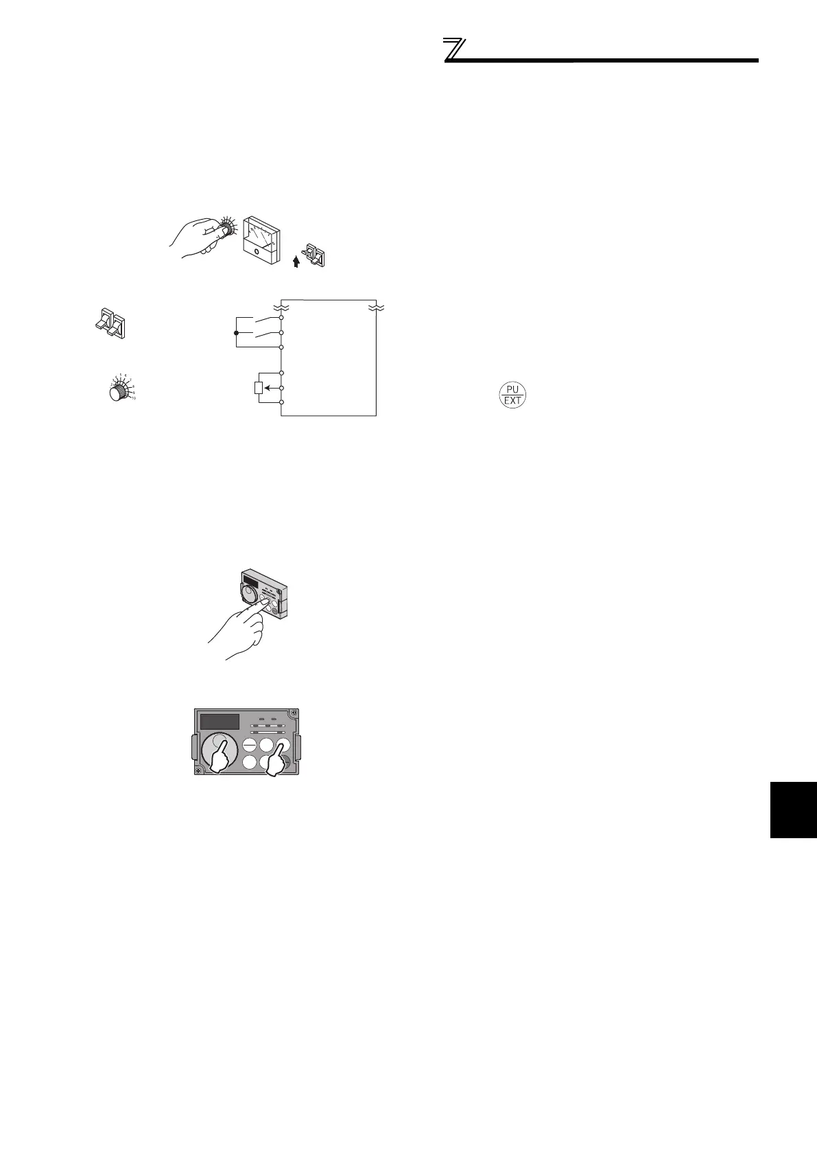
(4) External operation mode (setting "0" (initial value), "2")
(5) PU operation mode (setting "1")
Select the External operation mode when the start
command and the frequency command are applied
from a frequency setting potentiometer, start switch, etc.
externally and connecting them to the control circuit
terminals of the inverter.
Generally, parameter change cannot be performed in
the External operation mode. (Some parameters can be
changed. Refer to the detailed description of each
parameter.)
When "0" or "2" is selected for Pr. 79, the inverter enters
the External operation mode at power ON. (When using
the Network operation mode, refer to page 198.)
When parameter changing is seldom necessary, setting
"2" fixes the operation mode to External operation
mode. When frequent parameter changing is
necessary, setting "0" (initial value) allows the operation
mode to be changed easily to PU operation mode by
pressing of the operation panel. When you
switched to PU operation mode, always return to
External operation mode.
The STF and STR signal are used as a start command,
and the voltage or current signal to terminal 2, 4, multi-
speed signal, JOG signal, etc. are used as frequency
command.
Select the PU operation mode when applying start and
speed command by the key operation of the operation
panel (FR-DU07) or parameter unit (FR-PU04/FR-
PU07) alone. Also select the PU operation mode when
making communication using the PU connector.
When "1" is selected for Pr. 79, the inverter enters the
PU operation mode at power ON. You cannot change to
the other operation mode.
The setting dial of the operation panel can be used for
setting like a potentiometer. (Pr. 161 Frequency setting/key
lock operation selection, refer to page 311.)
When PU operation mode is selected, the PU operation
mode signal (PU) can be output.
For the terminal used for the PU signal output, assign
the function by setting "10 (positive logic) or 110
(negative logic)" in any of Pr. 190 to Pr. 196 (output
terminal function selection).
3
4
5
6
7
8
9
10
Hz
5
10
2
STF
STR
PC
Reverse rotation
start
Frequency setting
potentiometer
Inverter
Forward rotation
start
Operation panel
(FR-DU07)
 Loading...


