M800S/M80/E80 Series Connection and Setup Manual
4 General Specifications
108
IB-1501269-J
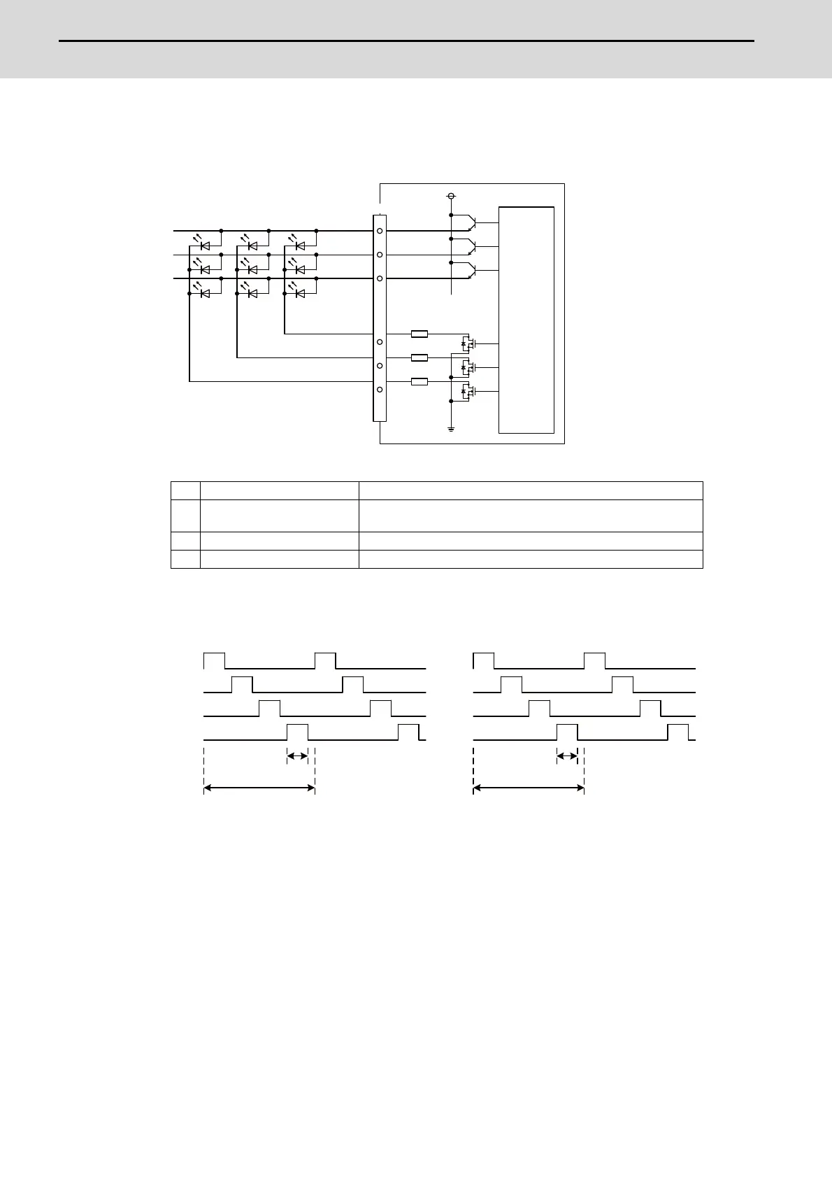
(b) Outline of scan output circuit
Output circuit
Output conditions
The common signals are switched over with scan output as shown in the following drawing. The LED
lights only when the common signal is High. As the common signal, four signals are switched in order,
and LED lights once every 5.84 ms for 1.28 ms.
1 Number of points 64 points
2 Configuration
Matrix of 4 common signals × 4 data signals +
4 common signals × 4 data signals
3 Rated voltage 5 VDC
4 Maximum output current 23 mA per point
5V
0V
:
:
:
:
OPKB
LC0A
LC1A
LC2A
LD0A*
LD1A*
LD2A*
:
:
:
:
100Ω
Control
circuit
LC0A
LC1A
LC2A
LC3A
LC0B
LC1B
LC2B
LC3B
5.84ms
1.28ms
5.84ms
1.28ms

 Loading...


