5 - 27
Chapter 5 Data Used for Positioning Control
Setting value, setting range
Setting value buffer memory
address
Item
Value set with GX Works2
Value set with sequence
program
Default value
QD77MS2
QD77MS4
QD77MS16
b0 Lower limit
b1 Upper limit
b2 Not used
b3 Stop signal
b4
External
command/
switching
signal
b5 Not used
b6
Near-point dog
signal
b7 Not used
b8
Manual pulse
generator input
(Note-1)
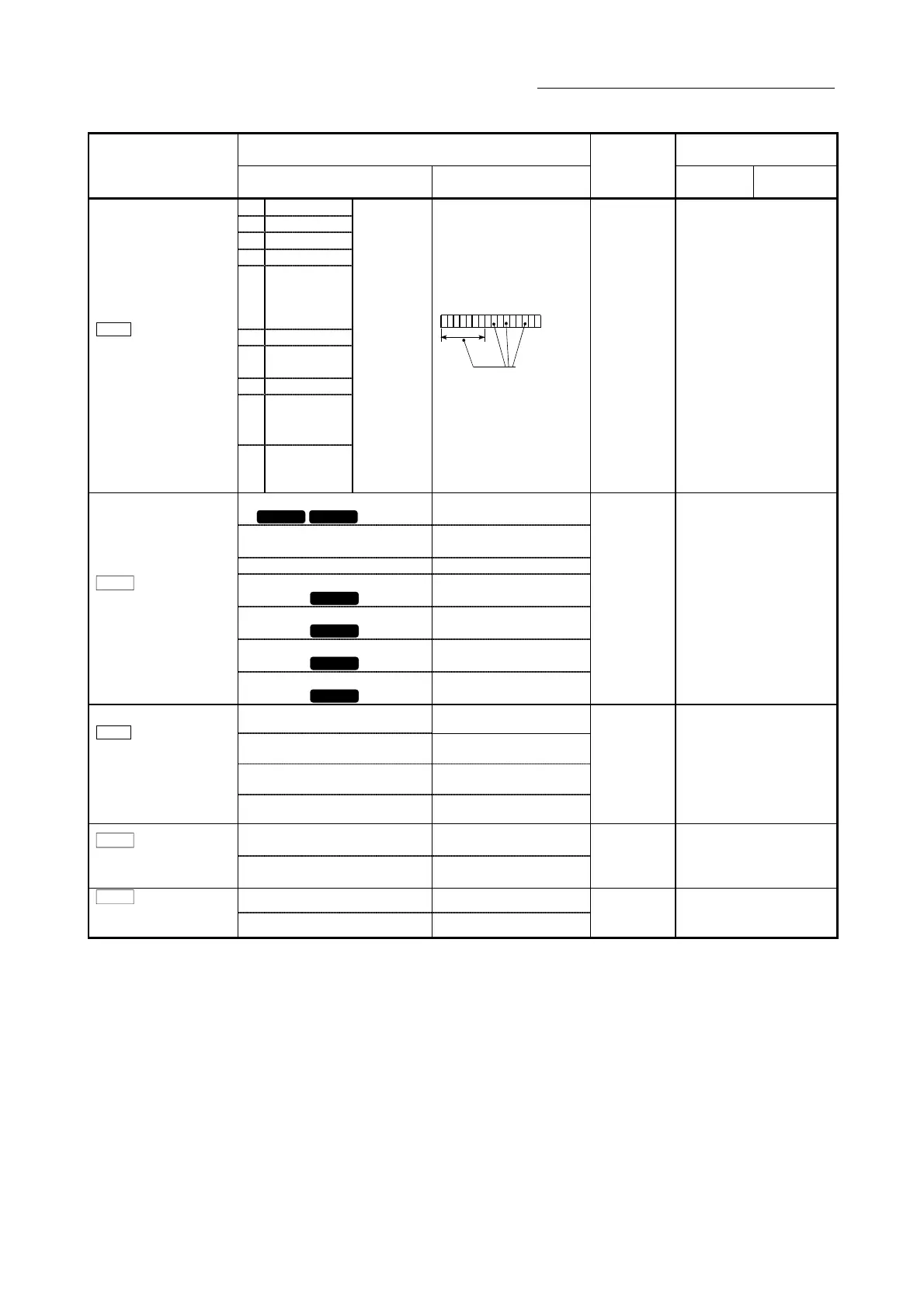
Pr.22
Input signal logic
selection
b9
to
b15
Not used
0: Negative
logic
1: Positive
logic
(Note-1):
Only the value
specified
against the
axis 1 is valid.
b0123456789101112131415
Always "0" is set to
the part not used.
0 31+150n
0: External input signal of QD77MS
QD77MS2 QD77MS4
0
1: External input signal of servo
amplifier
1
2: Buffer memory of QD77MS 2
3: External input signal 1 of
QD77MS
QD77MS16
3
4: External input signal 2 of
QD77MS
QD77MS16
4
5: External input signal 3 of
QD77MS
QD77MS16
5
Pr.80
External input signal
selection
6: External input signal 4 of
QD77MS
QD77MS16
6
QD77MS2 : 0
QD77MS4 : 0
QD77MS16: 1
32+150n
0: A-phase/B-phase multiplied by 4 0
1: A-phase/B-phase multiplied by 2 1
2: A-phase/B-phase multiplied by 1 2
Pr.24
Manual pulse generator/
Incremental
synchronous encoder
input selection
3: PLS/SIGN 3
0 33
0: Speed-position switching control
(INC mode)
0
Pr.81
Speed-position function
selection
2: Speed-position switching control
(ABS mode)
2
0 34+150n
0: Valid 0
Pr.82
Forced stop valid/invalid
selection
1: Invalid 1
0 35
n: Axis No.-1

 Loading...


