5 - 107
Chapter 5 Data Used for Positioning Control
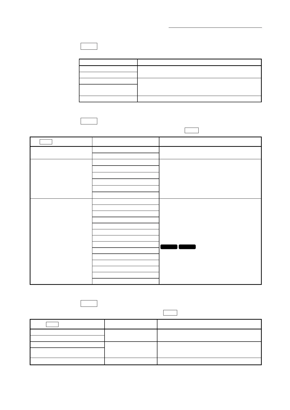
Da.15
Condition target
Set the condition target as required for each control.
Setting value Setting details
01H : Device X
02H : Device Y
Set the input/output signal ON/OFF as the conditions.
03H : Buffer memory (1-word)
04H : Buffer memory (2-word)
Set the value stored in the buffer memory as the condition.
03H: The target buffer memory is "1-word (16 bits)"
04H: The target buffer memory is "2-word (32 bits)"
05H : Positioning data No. Select only for "simultaneous start".
Da.16
Condition operator
Set the condition operator as required for the "
Da.15
Condition target".
Da.15
Condition target
Setting value Setting details
07H : DEV=ON 01H: Device X
02H: Device Y
08H : DEV=OFF
The state (ON/OFF) of an I/O signal is defined as the
condition. Select ON or OFF as the trigger.
01H :
∗∗
=P1
02H :
∗∗
P1
03H :
∗∗≤
P1
04H :
∗∗
≥
P1
05H : P1
≤∗∗≤
P2
03H: Buffer memory (1-word)
04H: Buffer memory (2-word)
06H :
∗∗≤
P1, P2
Select how to use the value (
∗∗
) in the buffer memory
as a part of the condition.
10H : Axis 1 selected
20H : Axis 2 selected
30H : Axis 1 and 2 selected
40H : Axis 3 selected
50H : Axis 1 and 3 selected
60H : Axis 2 and 3 selected
70H : Axis 1, 2, and 3 selected
80H : Axis 4 selected
90H : Axis 1 and 4 selected
A0H : Axis 2 and 4 selected
B0H : Axis 1, 2, and 4 selected
C0H : Axis 3 and 4 selected
D0H : Axis 1, 3, and 4 selected
05H: Positioning data No.
E0H : Axis 2, 3, and 4 selected
If "simultaneous start" is specified, select the axis
(or axes) that should start simultaneously.
QD77MS2 QD77MS4
Da.17
Address
Set the address as required for the "
Da.15
Condition target".
Da.15
Condition target
Setting value Setting details
01H : Device X
02H : Device Y
– Not used. (There is no need to set.)
03H : Buffer memory (1-word)
04H : Buffer memory (2-word)
Value
(Buffer memory address)
Set the target "buffer memory address".
(For 2 word, set the low-order buffer memory
address.)
05H : Positioning data No. – Not used. (There is no need to set.)

 Loading...


