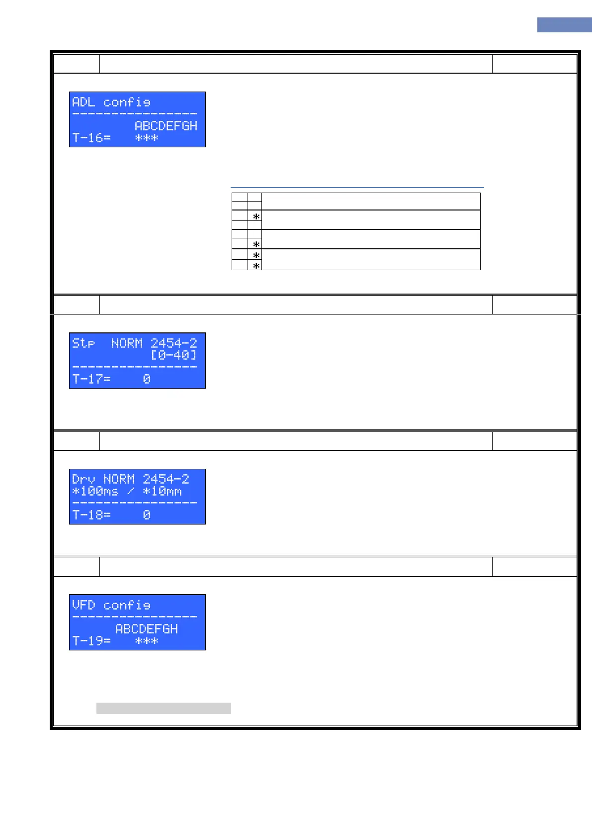
A – Drive direction (not selected – normal, selected – inverted)
B – Impulse direction (not selected – normal, selected – inverted)
C – Reset by CAN enable/disable (not selected – enable, selected – disable)
D – Contactor status signal transfer from ADL by CAN (not selected – enable,
selected – disable)
E – Brake status signal transfer from ADL by CAN (not selected – enable, selected
– disable)
F – ADL ready signal transfer from ADL by CAN (not selected – enable, selected –
disable)
Positioning system by encoder on ADL enable with resolution 1
Impulses = impulses / 1
Positioning system by encoder on ADL enable with resolution 2
impulses = impulses / 2
Positioning system by encoder on ADL enable with resolution 3
impulses = impulses / 4
Positioning system by encoder on ADL disable (another source of
impulses in use)
After activation of input FI-312 elevator reach the station which is defined
with parameter T-17, without opening the doors, descent automatically
elevator for lenght which is define by parameter T-18, open the doors and
waiting with opened doors until deactivated input FI-312, then start normal
travel.
While the function FI-312 is activated, elevator don't accept landing and
cabin calls.
Drv NORM 2454-2 * 100ms / *10mm
Defining times / descent time in the zone test.
(For the absolute possitioning type - descent is T-18 x 10 mm)
(For other positioning type – descent length was determined by the T-18 x
100 ms)
A – enable phase control through LC100-VFD card
B – enable evacuation detection through LC100-VFD card (only in
combination with selected letter A)
C – Reserved
D – Reserved
E – Reserved
F – Reserved
G – Reserved
H – Reserved
In firmware 4.409.00 or newer.