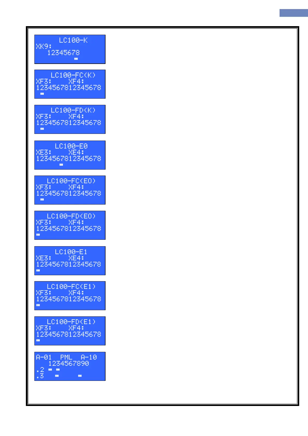
Status of output signals on LC100-K board for connector XK9. Display exist
only if the LC100-K board is included through parameter A-06.
Status of input/output signals on LC100-F board adress „C“ connected to
LC100-K board for connectors XF3 and XF4. Display only exist if the LC100-F
board adress „C“ is included through parameter A-06.
Status of input/output signals on LC100-F board adress „D“ connected to
LC100-K board for connectors XF3 and XF4. Display only exist if the LC100-F
board adress „D“ is included through parameter A-06.
Status of input output signals on LC100-E board adress „0“ for connectors
XE3 and XE4. Display only exist if the LC100-E board adress „0“ is included
through parameter A-07.
Status of the input/output signals on LC100-F board adress „C“ conected
to LC100-E board adress „0“ for connector XF3 and XF4. Display only exist if
the LC100-F board adress „C“ is included through parameter A-07.
Status of the input/output signals on LC100-F board adress „D“ conected
to LC100-E board adress „0“ for connector XF3 and XF4. Display only exist if
the LC100-F board adress „D“ is included through parameter A-07.
Status of input output signals on LC100-E board adress „1“ for connectors
XE3 and XE4. Display only exist if the LC100-E board adress „1“ is included
through parameter A-08.
Status of the input/output signals on LC100-F board adress „C“ conected
to LC100-E board adress „1“ for connector XF3 and XF4. Display only exist if
the LC100-F board adress „C“ is included through parameter A-08.
Status of the input/output signals on LC100-F board adress „D“ conected
to LC100-E board adress „1“ for connector XF3 and XF4. Display only exist if
the LC100-F board adress „D“ is included through parameter A-08.
Status of the input/output signals on LC100-P, M or L boards for pins 2 and
3 on connector XP3 or XM3. A-10 means first ten adreses of P or M boards on
side „A“. Second row presents floor, third row is status of the pin 2, fourth row
is the status of the pin 3. Display only exist if the P or M boards are included
through parameter A-09.