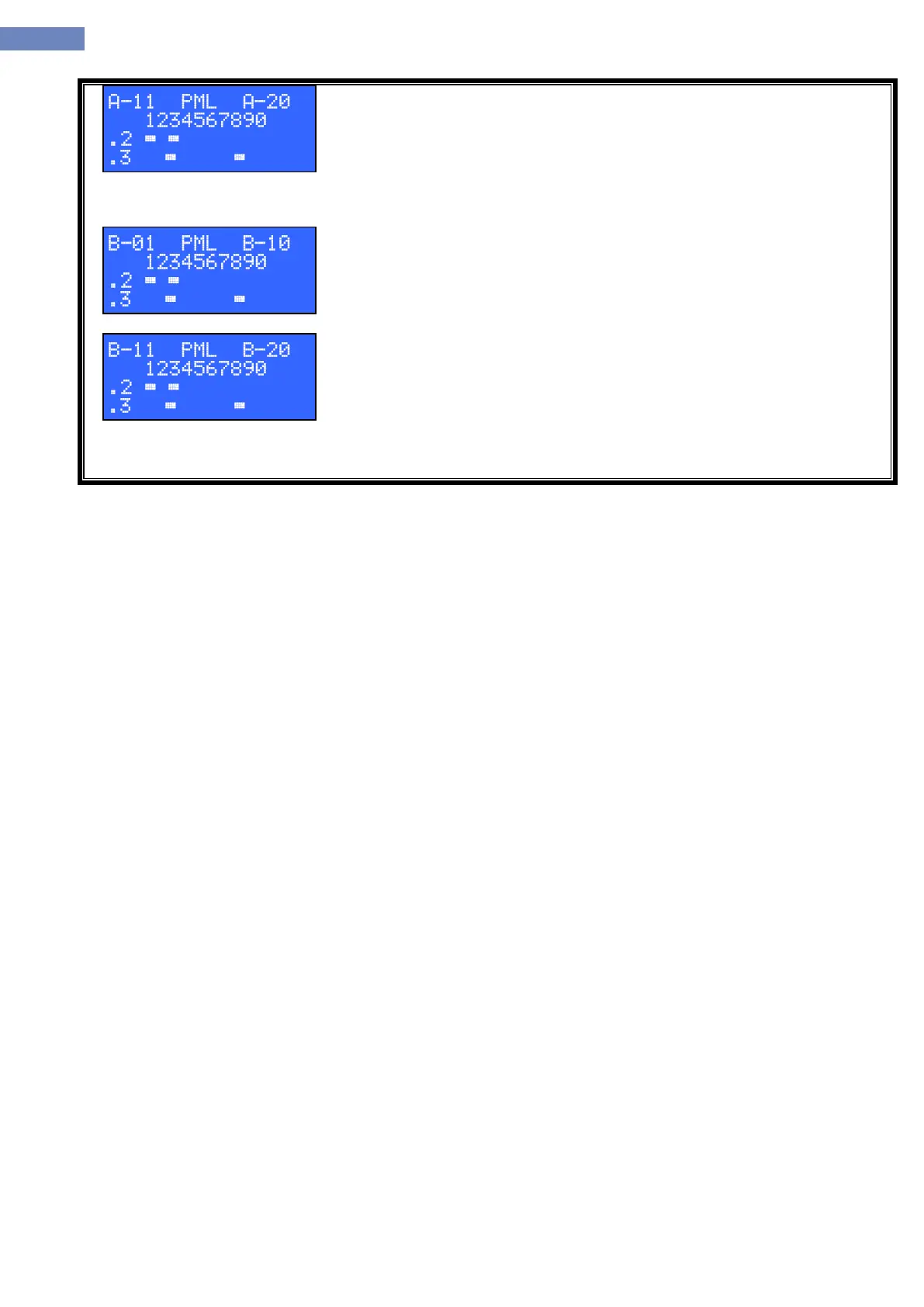
Status of the input/output signals on LC100-P, M or L boards for pins 2 and
3 on connector XP3 or XM3. A-20 means second ten adreses of P or M boards
on side „A“. Second row presents floor 1=adress 11, 2=adress 12, ond so on.
Third row is the status of the pin 2, fourth row is the status of the pin 3. Display
only exist if the P or M boards are included through parameter A-09.
Next dysplay is A-30 which is status for adresses 21 to 30 same as for A20,
than also A-40 for adresses 31 to 40.
Status of the input/output signals on LC100-P, M or L boards for pins 2 and
3 on connector XP3 or XM3. B-10 means first ten adreses of P or M boards on
side „B“. Second row presents floor, third row is status of the pin 2, fourth row
is the status of the pin 3. Display only exist if the P or M boards are included
through parameter A-09.
Status of the input/output signals on LC100-P, M or L boards for pins 2 and
3 on connector XP3 or XM3. A-20 means second ten adreses of P or M boards
on side „B“. Second row presents floor 1=adress 11, 2=adress 12, ond so on.
Third row is the status of the pin 2, fourth row is the status of the pin 3. Display
only exist if the P or M boards are included through parameter A-09.
Next dysplay is B-30 which is status for adresses 21 to 30 same as for B-
20, than also B-40 for adresses 31 to 40.