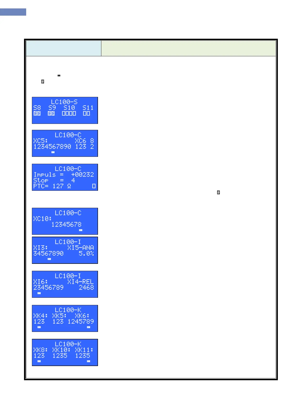
Input/output menu is used to monitor status of the inputs-outputs of all boards in the system. First row shows
the LC100 board. Second row displays connector, third row displays pin on the connector. In the fourth row under
the pin sign means that the input/output is active, active status for the safety circuit and PTC is shown with the
sign
Chosing the input/output is done by pressing the „Left“ or „right“ button.
Status of the input signals on LC100-S board, for connectors XS8, XS9,
XS10 and XS11. On the example XS8 and XS9 are active, other inputs are not
active.
Status of the input signals on LC100-C board for connectors XC5, XC6 and
XC8
Status of the counter for inductive switch (input XC7.3). Every thime the
drive is reset status of the counter is set to 00000. When driving down the
counter counts backwards and when driving up counter counts foward.
Third row displays active floor.
Fourth row displays resistance of the motor PTC probe and the status of
the PTC input XC8.2. Active input is presented with sign and means that the
probe resistance reached the limit defined with the parameter I-02.
Status of the output signals on the LC100-C board for the connector XC10.
Status of the input signals on LC100-I board for connector XI3, and status
of the analog output XI5. Display exist only if the LC100-I board is included
through parameter A-05.
Status of the output signals on LC100-I board for conector XI6, and status
of the relay outputs XI4. Display exist only if the LC100-I board is included
through parameter A-05.
Status of the input signals on LC100-K board for connectors XK4, XK5 and
XK6. Display exist only if the LC100-K board is included through parameter A-
06.
Status of the input signals on LC100-K board for connector XK8, and status
for input signals for connectors XK10 and XK11. Display exist only if the LC100-
K board is included through parameter A-06.