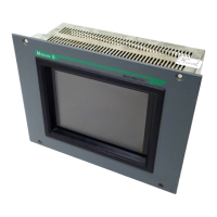
Device Description MV4-570-TA1/2, MV4-590-TA1/2 2-3
Moeller 07/01 AWB-C2700-1347GB
CONTENTS
1 Introduction.............................................................................................................................................. 2-4
2 Device version......................................................................................................................................... 2-4
3 Scope of delivery..................................................................................................................................... 2-5
4 EC Conformity ......................................................................................................................................... 2-6
5 Technical Data......................................................................................................................................... 2-6
6 Dimensions, Views, Front Plate Cutout................................................................................................... 2-8
6.1 General mounting instructions ......................................................................................................... 2-8
6.2 Dimensions 10.4″- unit MV4-570-TA1/2(-xx1) ................................................................................. 2-9
6.3 Front panel cutouts for 10.4″ units ................................................................................................. 2-10
6.4 Dimensions for 13.8″ unit - MV4-590-TA1/2(-xx1) ......................................................................... 2-12
6.5 Front cover cutout for 13.8″ units................................................................................................... 2-13
7 Connection Assignment ........................................................................................................................ 2-14
7.1 System power supply for AC Versions (100 to 240 V AC, TA2 units) ........................................... 2-14
7.2 System power supply for DC Versions (24 V DC, TA1-units)........................................................ 2-14
7.3 System Port (Function, Assignment).............................................................................................. 2-15
8 Memory Card Slot.................................................................................................................................. 2-15
9 The Touch Screen................................................................................................................................. 2-16
9.1 Basic function of the Touch Screen ............................................................................................... 2-16
9.2 Power up function test.................................................................................................................... 2-16
9.3 Cleaning and care of the Touch Screen......................................................................................... 2-16
10 Function and control LEDs ................................................................................................................ 2-17
11 Communication Modules and System Expansion (Slot 0, Slot 1) ..................................................... 2-18
12 Installation Instructions ...................................................................................................................... 2-19
12.1 Device installation .......................................................................................................................... 2-19
12.2 Mounting to IP 65 ........................................................................................................................... 2-19
12.3 Preparation of the connection cables (EMC) ................................................................................. 2-20
12.4 Preparing the shield connections................................................................................................... 2-21

 Loading...