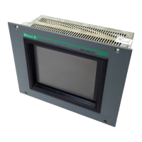
Device Description MV4-670-TA1/2, MV4-690-TA1/2 3-3
Moeller 07/01 AWB-C2700-1347GB
CONTENTS
1 Explanation of Symbols ........................................................................................................................ 3-4
2 Introduction........................................................................................................................................... 3-5
3 Device Versions / Type Designation..................................................................................................... 3-5
3.1 Scope of Delivery ............................................................................................................................ 3-6
4 Device Mounting................................................................................................................................... 3-7
4.1 General mounting instructions......................................................................................................... 3-7
4.2 Dimensions for 10.4″ devices.......................................................................................................... 3-8
4.3 Front panel cutouts for 10.4″ devices.............................................................................................. 3-9
4.4 Dimensions for 15″ devices........................................................................................................... 3-10
4.5 Front panel cutouts for 15″ devices............................................................................................... 3-11
5 Mounting Instructions ......................................................................................................................... 3-12
5.1 Installation according to degree of protection IP65 ....................................................................... 3-12
6 Overview of the Connections and the Connector Panel..................................................................... 3-13
7 Connecting the System Power Supply ............................................................................................... 3-14
7.1 System power supply AC (100...240VAC 50/60Hz) Type MV4-670/690-TA2(-xx1)...................... 3-14
7.2 DC system power supply, isolated (24VDC) Type MV4-670/690-TA1(-xx1)................................. 3-15
8 Interface Connections and Cabling .................................................................................................... 3-16
8.1 Preparing the connection cable (EMC) .........................................................................................3-16
8.2 Preparing the shield connections .................................................................................................. 3-17
9 Connecting the Parallel Port............................................................................................................... 3-18
10 Connecting the Ethernet Interface...................................................................................................... 3-19
11 Connecting the System Port (serial, RS232)...................................................................................... 3-20
12 Download Button ................................................................................................................................ 3-20
13 Communication Cards and System Slot............................................................................................. 3-21
14 Expansion and Configuration Options................................................................................................ 3-22
14.1 System interventions .................................................................................................................. 3-22
14.2 Auxiliary voltage output on the System port (5V)........................................................................ 3-22
15 Memory Card Slot............................................................................................................................... 3-23
16 Function and Control LEDs ................................................................................................................ 3-24
17 Touch Screen ..................................................................................................................................... 3-25
17.1 Basic Touch Screen function...................................................................................................... 3-25
17.2 Power up function test ................................................................................................................ 3-25
17.3 Cleaning and maintenance of the Touch Screen ....................................................................... 3-25
18 Display Technology, Backlight............................................................................................................ 3-26
19 Maintenance and Repair .................................................................................................................... 3-26
20 Disposal.............................................................................................................................................. 3-26
21 Technical Data.................................................................................................................................... 3-27
22 EC Conformity .................................................................................................................................... 3-29

 Loading...