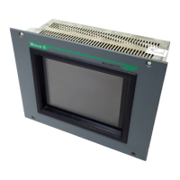
Device Description MV4-670-TA1/2, MV4-690-TA1/2 3-20
Moeller 07/01 AWB-C2700-1347GB
11 Connecting the System Port (serial, RS232)
The system port is a standard RS232 interface. The interface is not isolated. The GND connection is directly
connected to the housing potential (→ Section 21).
Cables connected to the system port must be laid separately from the low-voltage cables.
If required, pin 9 can be assigned to the +5V supply (→ Section 21).
12 Download Button
The Download button is used to activate the runtime system functions. Refer to the design software
documentation for more information on the function of the Download button.
The Download button is located on the rear of the MV4. Ensure the accessibility of the device when it is
mounted.
A serial download of a project with the ZB4-244-KP1 cable is not possible on the MV4-600 devices. This
function is possible however, via the Ethernet interface.
SYSTEM PORT
Sub-D 9 Pole male
Pin
No.
Assignment Function
1 - Not assigned
2 RxD Receive data
3 TxD Transmit data
4 DTR Data terminal ready
5 GND Ground
6 DSR Ready for operation
7 - Not assigned
8 - Not assigned
9(+5V)
+5V supply (→ Section 11)
Case Shield Cable shield

 Loading...