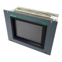
Device Description MV4-570-TA1/2, MV4-590-TA1/2 2-19
Moeller 07/01 AWB-C2700-1347GB
12 Installation Instructions
12.1 Device installation
When installing the Touch Operator Panel, a minimum distance of 10 cm must be ensured between the
device and any other components, so that the cooling of the system is not impaired. The cooling slits must
not be covered by cables or other objects.
The specified operating temperature (see Section 5) is based on a vertical mounting with unhindered air
convection and a location of no more than 2000 m above sea level.
Avoid the exposure of the flat screen to direct sunlight. The radiation from the sun (UV component)
reduces the lifespan of the liquid crystal.
12.2 Mounting to IP 65
a) Installation of the unit with 4-hole aluminium front
For installations requiring IP 65 compliance the supplied conter frame and seal must be used.
These ensure the necessary pressure required for mounting in thin panels.
Special care should be taken during mounting to ensure correct sealing to IP 65.
1. Fit the front seal from the rear of the device.
2. Insert the unit into the panel cutout from the.
3. The front seal must fit evenly between the front plate and the front panel.
4. Fit the conter frame from the rear of the device.
5. Tighten the countersunk screws on the device through the front panel onto the conter frame.
The countersunk screws must be tightened uniformly and securely.
6. Ensure the correct positioning and even pressure of the front seal.
Observe the general mounting instructions (refer to section 6.1).

 Loading...