T200 User's Manual SECTION 6: T200 FUNCTIONAL OVERVIEW
PAGE 6-50
6.7.3.11 Monitoring the Position Tracking in CAN Interpolation Mode
The T200 also provides monitoring of the position error in CAN Interpolation mode. Two parameters are provided for
the user to configure this tracking. These are:-
§ Static Loop Position Error Band:- This quantity is specified in position increments (see Section 7.10.1.3 CAN
Position Scaling for an explanation of the scaling). It is the maximum allowed position error that the user can allow
when the drive is not moving or moves at a very low velocity. The Static Loop Position Error Band can be
programmed using the STS Hand Held terminal command.
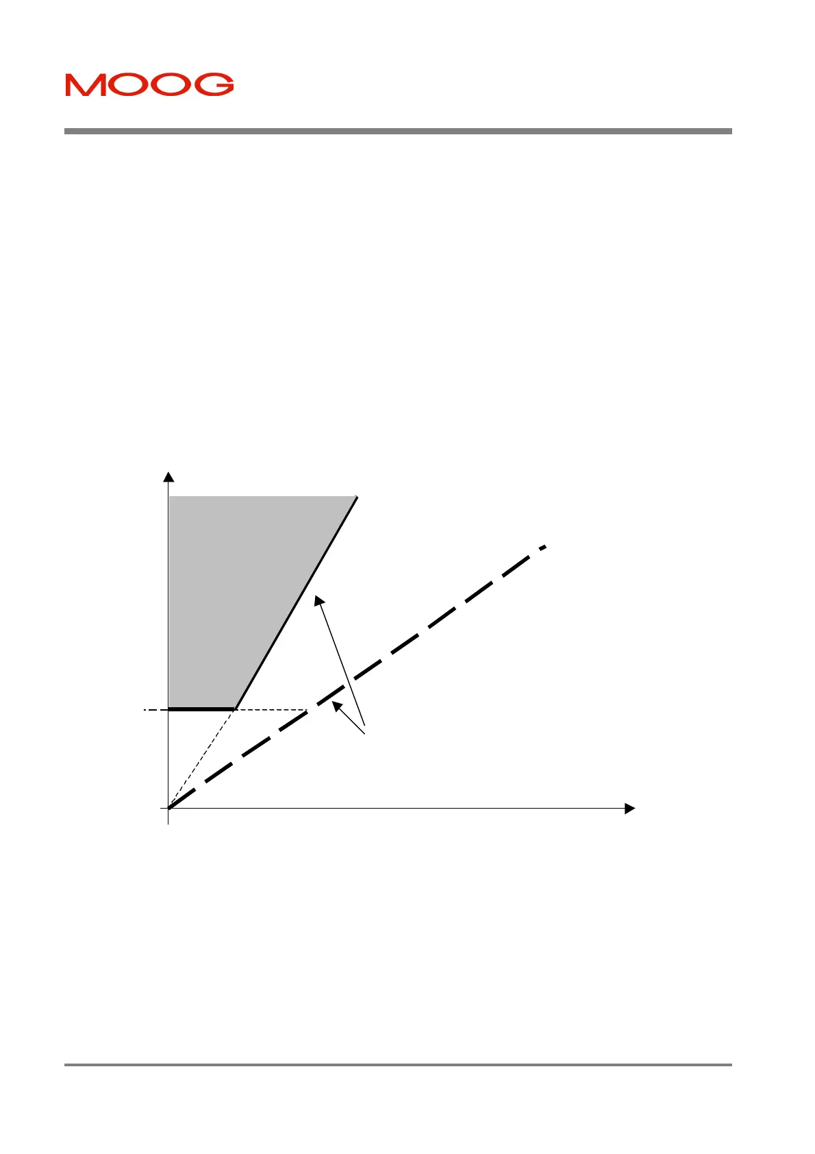
§ Dynamic Loop Position Error is the ratio of the slopes of the two lines shown in the Figure 6.22 below. A
position system that has no velocity feed-forward term will have a position error that is proportional to the actual
velocity. The Dynamic Loop Position Error in effect implies how many times greater a position error than this
expected position error, the user will tolerate in his application. Note that this parameter can be set to a value less
than 100%, for a system which uses velocity feed-forward terms (CAN systems use feed-forward terms, to reduce
the position loop error).
The warning condition will be indicated on the T200's seven-segment display, if the position error exceeds the Position
Error Allowed (see diagram below).
Figure 6.22:- Position Error Monitoring
Actual Velocity
Actual Position
Error
Position Error
Allowed as a
function of
velocity, with no
warning
Expected Position
Error of a positioning
system with no
velocity feedforward
Static
Position
Error
Dynamic Error gives
difference in slopes
Operating area in
which the Position
Error Warning is
set
Artisan Technology Group - Quality Instrumentation ... Guaranteed | (888) 88-SOURCE | www.artisantg.com