SECTION 6: T200 FUNCTIONAL OVERVIEW T200 User's Manual
PAGE 6-9
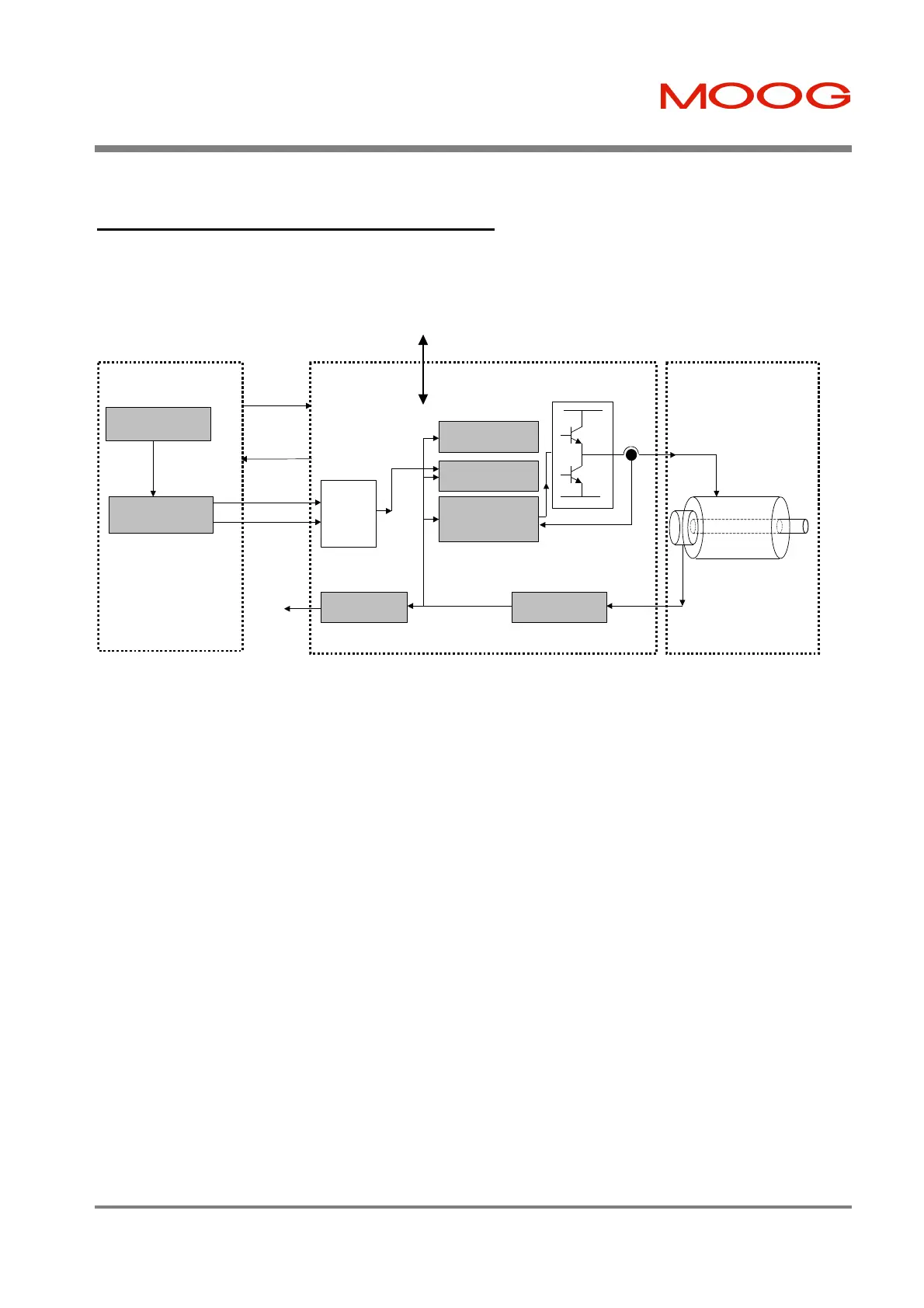
6.2.4 Digital Inputs Velocity Interface Mode
The T200 generates its velocity command as a function of the state of two digital inputs.
Velocity Control
Position Control
Vector-Controlled
Torque/Current
Loops
Resolver
Position
3-Phase
Motor
Resolver to Digital
System Motion
Controller
Velocity Command
Generation
Digital Outputs
Digital
Reference
Interface
Function
PROG_SPD0
RS232 / RS485
Moog T200 Moog Motor
Actual
Motor
Position
PROG_SPD1
Control
Signalling:-
ENABLE
PWR_RDY
AUTO_MAN
TRQ_VEL
CW_LIM
CCW_LIM
BRK_IP
ROT_DIR
THRM_LIM
DRV_ENBLD
SPD/TRQ_ACHVD
Figure 6.4:- Digital Velocity Reference Mode Block Diagram
Note that the ENABLE, PWR_RDY and AUTO_MAN inputs are used consistently for all control modes.
• The user can program the 4 speeds at which the T200 can be operated.
• The drive behaves as a standard analog interface drive in other respects, as described under Section 6.1.1.
Artisan Technology Group - Quality Instrumentation ... Guaranteed | (888) 88-SOURCE | www.artisantg.com