T200 User's Manual SECTION 7: WINDRIVE
PAGE 7-50
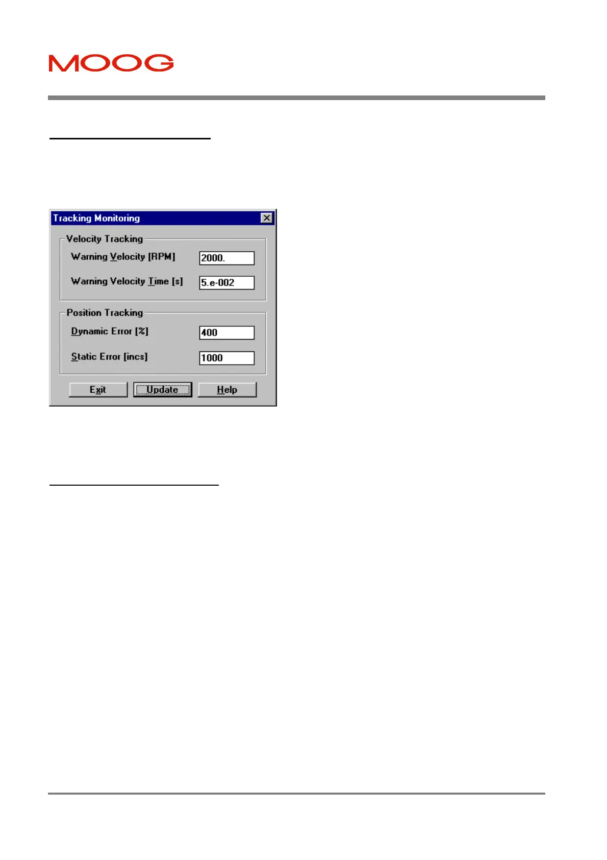
7.11.6 Tracking Monitoring
The Tracking Monitoring dialog box is available from the Tuning dialog box. This dialog is used to set warning
thresholds, such that if these thresholds are exceeded, the T200 will flag the warnings to users via the 7-segment display,
and through feedback via the CAN channel.
Figure 7.52: Tracking Monitoring Dialog Box
7.11.7 Position Loop Tuning
After completing drive configuration as per Section Drive Set-up, the user must tune the position loop to optimize
position loop tracking and disturbance rejection performance. This section provides a recommended Position Mode
tuning procedure for use with WinDrive. Note that a generic position loop tuning procedure (WinDrive or the Hand
Held Terminal interfaces can be used with this procedure) is given in Section 6.6.3. The procedure should be followed in
the sequence listed, noting all warnings appropriately. Position Mode should be selected from the Tuning dialog box
(see Section Control Mode Selection). Again tuning can be carried out in Reduced Power Mode (Manual Mode) where
there is a concern about safety.
The recommended practise for tuning the Position Loop is:
1. First tune the Velocity Loop by following Section Velocity Loop Tuning. The Velocity Observer can also be used to
increase Velocity Loop Gains, by following Section 7.11.4.1 Velocity Estimation. Note that the Auto Tuner can be
used to adjust the Velocity Loop Gains.
2. Change the control mode to Position Mode (see Section Control Mode Selection). Now tune the Position Loop Gain
using the procedure described in Section 6.6.3.
Tuning of the Position Loop Gain is facilitated by use of the Data Logger (see Section Data Logger) and the T200's
built-in Function Generator. Set the Data Logger to record Reference Velocity on Channel 1 and Error Position Low
on Channel 2. Set the Reference Source to the Function Generator with appropriate Distance, Acceleration, Speed
Amplitude and Period parameters.
Velocity Tracking: The Velocity Error is the difference
between the velocity command and the Actual Velocity. The
Velocity Following Error warning will be set if the absolute
value of the error velocity exceeds the Warning Velocity for
the Warning Velocity Time.
Position Tracking: The Position Error is the difference
between the position command and the Actual Position. The
Position Following Error warning will be set
1. if the absolute value of the position error exceeds a
quantity equal to
Actual Velocity • Dynamic Error/(100 • Position
Loop Gain).
This quantity is the expected Position Error of a
position loop with no Velocity Feedforward
compensation, multiplied by the Dynamic Error
factor.
or,
2. if the absolute value of the Position Error exceeds the
Static Error (expressed as position increments - see
Section 7.10.1.3 Reference Source Selection, CAN
Reference Source, CAN Position Scaling).
Artisan Technology Group - Quality Instrumentation ... Guaranteed | (888) 88-SOURCE | www.artisantg.com