T200 User's Manual SECTION 6: T200 FUNCTIONAL OVERVIEW
PAGE 6-64
6.10 Encoder Simulation Function
The Encoder Simulation generates incremental encoder formatted output signals from a resolver position transducer.
See Section 3.17 for an electrical description of the interface. The following signals are generated:-
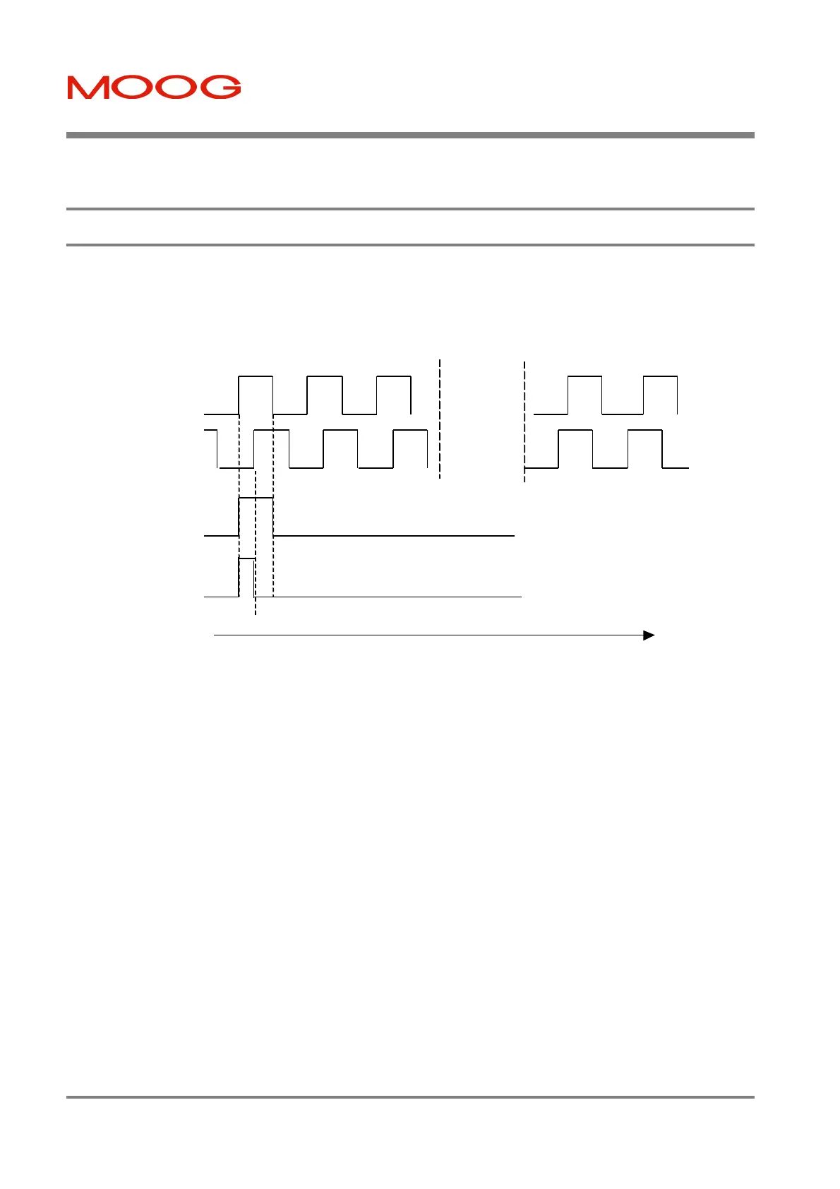
Figure 6.24:- Encoder Simulation Signals on Connector J7
The T200 implements two types of encoder simulation:-
1. High Bandwidth Encoder Simulation ("ESM3"):- This mode is recommended when the T200 is used in torque
mode. The encoder simulation is carried out directly via analog hardware, with a feedback bandwidth of between
800 and 1000Hz. In this case the Number of Lines per Revolution is limited to the values 128, 256, 512 or 1024.
2. Flexible Line Count Encoder Simulation ("ESM1"):- This mode is recommended when the T200 is used in
velocity mode. In this case the encoder simulation is implemented as a hybrid hardware and software module, and
the feedback bandwidth is limited to approximately 400Hz.
The user must set the Number of Lines per Revolution parameter to an even number between 128 and 8192. If the User
sets the Number of Lines per Revolution to a value of 128, 256, 512 or 1024, then the high bandwidth solution is chosen.
If the user selects any other value then option 2) above is selected automatically by software. For both options 1) and 2)
above the following software configurable options are available:-
§ Zero-Marker-Offset:- The user may specify an offset (in mechanical motor shaft degrees) of the Zero-Marker of the
Encoder Simulation output, with respect to the motor’s own resolver-position sensor natural zero position.
§ Marker-Length:- Long Marker and Short Marker (see Figure 6.24 above) options are provided, as user selectable
items.
Increasing Motor Shaft
Position
(ESM) A
(ESM) B
Long Zero
MARKER
Short Zero
MARKER
Clockwise Counter-Clockwise
A leads B B leads A
Artisan Technology Group - Quality Instrumentation ... Guaranteed | (888) 88-SOURCE | www.artisantg.com