SECTION 1: T200 OVERVIEW T200 User's Manual
PAGE 1-13
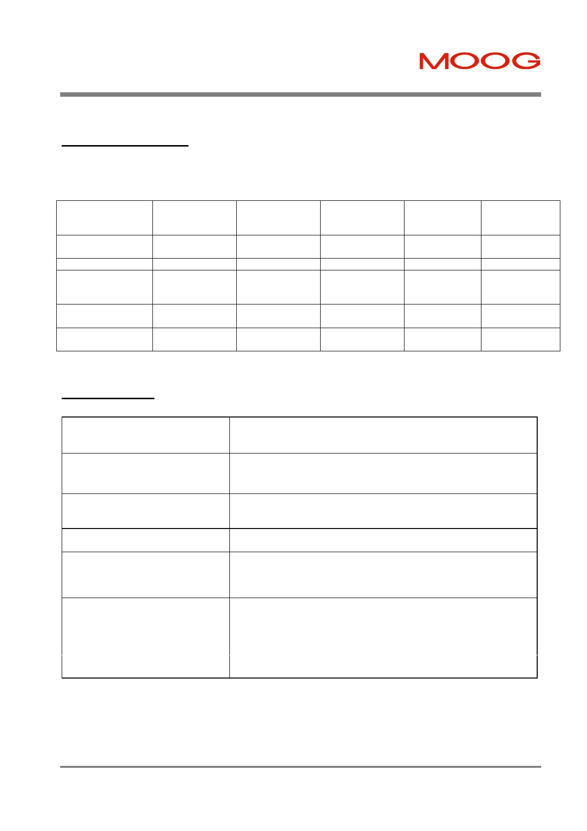
1.6.2 Digital Outputs
• All outputs are Optically Isolated.
• Maximum ratings of 36V, 50mA.
• Pull-Up or Pull-Down from O_COMMON line.
J1 Pin Name
(Pin Number)
10V Torque or
Velocity Analog
Reference
Stepper
Interface Mode
Digital Inputs
Speed Mode
CAN-Profile,
Inter-polation
Mode
Point Mode
THRM_LIM
(19)
Limit Activated Limit Activated Limit Activated Limit Activated Limit Activated
DRV_ENBLD (20) Drive Enabled Drive Enabled Drive Enabled Drive Enabled Drive Enabled
SPD/TORQ_
ACHVD
(21)
Speed/Torque
Achieved
Position
Following Error
Speed/Torque
Achieved
Speed/Torque
Achieved
General purpose
output
SPARE_DIG_OP_1
(27)
Fault Code Bit Fault Code Bit Fault Code Bit User defined General purpose
output
SPARE_DIG_OP_2
(28)
Fault Code Bit Fault Code Bit Fault Code Bit User defined General purpose
output
Table 1.8: T200 Digital Outputs Overview
1.6.3 Other I/O
2 Analog Inputs
Analog Command (±10V, 12 bit, 10kΩ input impedance)
Analog Torque Limit (± 10V, 12 bit, 10Ω input impedance)
2 Analog Outputs
Programmable Test Point 1 (± 10V, 12 bit, 100Ω output impedance)
Programmable Test Point 2 (± 10V, 12 bit, 100Ω output impedance)
Brake Control
3,5A, 30Vd.c. relay provided. Switched under user control or T200
software control.
Motor Position Feedback Type
Resolver Based
Incremental Encoder Interface
1 channel
1MHz RS422 Channel Input
5V/100mA power output with resettable fusing.
Communications Interfaces Controller Area Interface
CANOpen (ISO11898) hardware-interface format (RS485 interface also
included on spare pins of 9 Way Sub-D Connector. See Section 9.)
Optically Isolated (internally supplied power)
5kBaud to 1MBaud programmable
RS232 Interface at 9600Baud
RS485 Interface at 9600Baud
Table 1.9: T200 Miscellaneous I/O Summary
Artisan Technology Group - Quality Instrumentation ... Guaranteed | (888) 88-SOURCE | www.artisantg.com