SECTION 6: T200 FUNCTIONAL OVERVIEW T200 User's Manual
PAGE 6-7
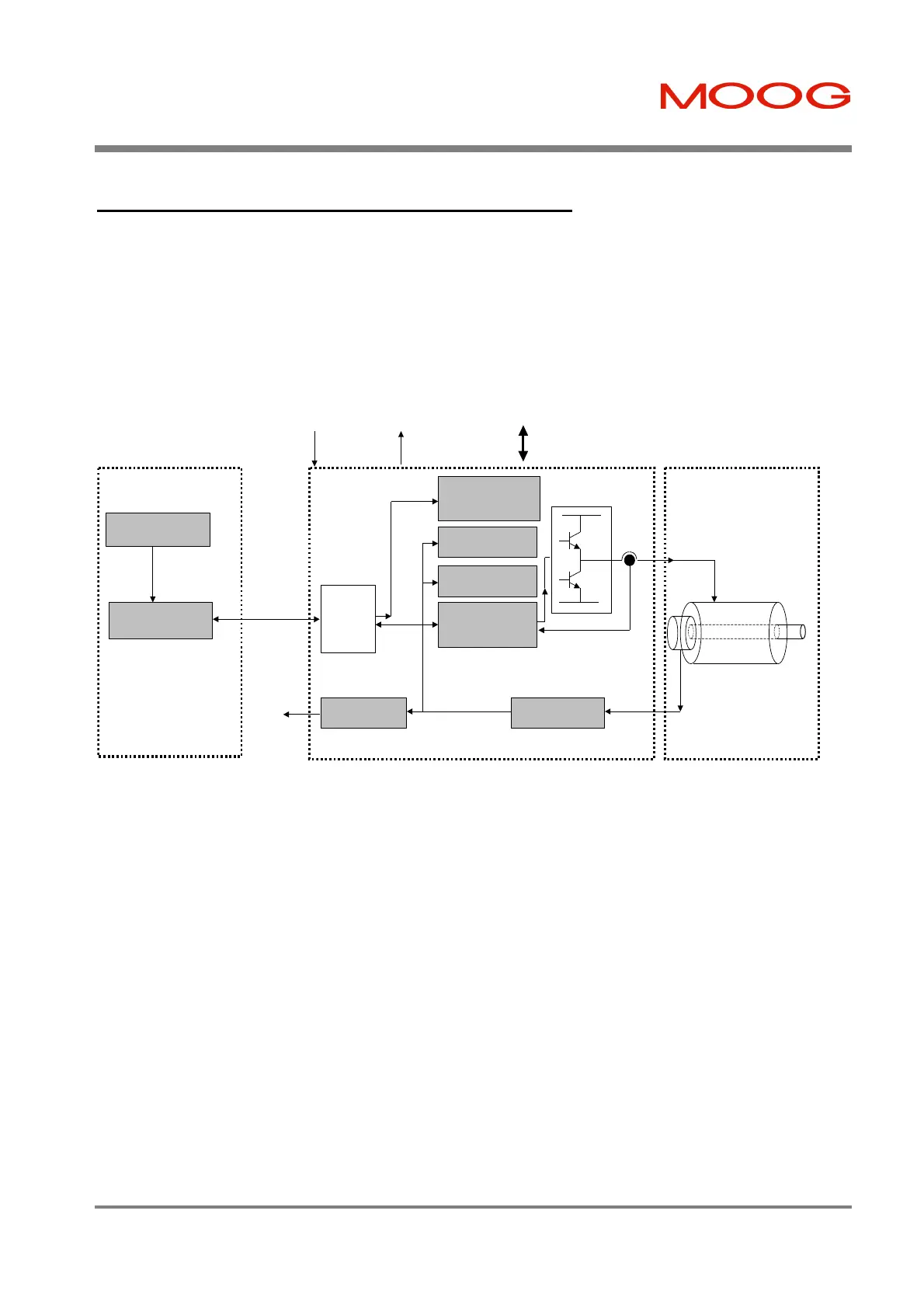
6.2.2 Controller Area Network (CAN) Interface Mode
The T200 provides a CAN fieldbus connection. The CAN interface provides:-
• Set-up of all drive parameters using a standard communications protocol (CANOpen).
• High-speed transfer of process and status information. This removes the need for extensive interconnect between
the T200 and the System Motion Controller.
Velocity Control
Position Control
Vector-Controlled
Torque/Current
Loops
Resolver
Position
Motor
Resolver to Digital
System Motion
Controller
Position Command
Generation
CAN Interface
CAN
Interface
Function
RS232 / RS485
Moog T200
Moog Motor
Actual
Motor
Position
CAN Cable
Position Interpolation
and Trajectory
Generator Function
Control Signalling (to/from
Machine Safety and Indication I/O)
ENABLE
PWR_RDY
AUTO_MAN
CW_LIM
CCW_LIM
BRK_IP (tied high)
HOME THRM_LIM
Q-STOP DRV_ENBLD
Figure 6.2:- CAN Interface Mode System Diagram
Note that the ENABLE, PWR_RDY and AUTO_MAN inputs are used consistently for all control modes.
• Each T200 has network node identification switches provided on their front panel, such that each node may be
addressed uniquely via the CAN interface
• Motor configuration, control modes, control loop gains and other parameterisation information can be read from and
written to the T200. Extensive diagnostic information and fault history data can also be read back and analysed by
the System Motion Controller. Data sequences can be logged using complex trigger conditions and transmitted
back to the System Motion Controller.
• The T200 provides several positioning and velocity modes when operated via the CAN interface:-
1. Interpolation Mode. The System Motion Controller transmits target positions at high data rates, and the T200
finely interpolates these positions to follow the target trajectory.
2. Point to Point Mode. The System Motion Controller transmits a target position, velocity and acceleration via
the CAN interface. The T200 generates a smooth trajectory to the target position using this data.
3. Gearing Mode. A 'master' T200 generates a 'Master-Angle' position reference at a high rate. One or many
T200 'slaves' receive this reference. These slaves multiple the 'Master-Angle' by a user programmed factor,
and use the result as their command position.
4. Camming Mode. Slave T200's simulate a mechanical cam with high precision. Slave T200's transform the
'Master-Angle' through a user defined cam shape, and use the result as their command position.
5. Velocity Mode. The T200 operates in velocity mode, with the command velocity and torque limit transmitted at
high speed via the CAN interface.
Artisan Technology Group - Quality Instrumentation ... Guaranteed | (888) 88-SOURCE | www.artisantg.com