ioLogik E2210 User’s Manual Using ioAdmin
3-8
To control switch bounces, the ioLogik E2210 provides software filtering. It is configurable in multiples
of 0.5 ms. For example, a setting of 2 would mean a 1 ms filter (2 x 0.5 ms). The maximum value allowed
by the software filter is 65535.
NOTE: “1” is the minimum filter value.
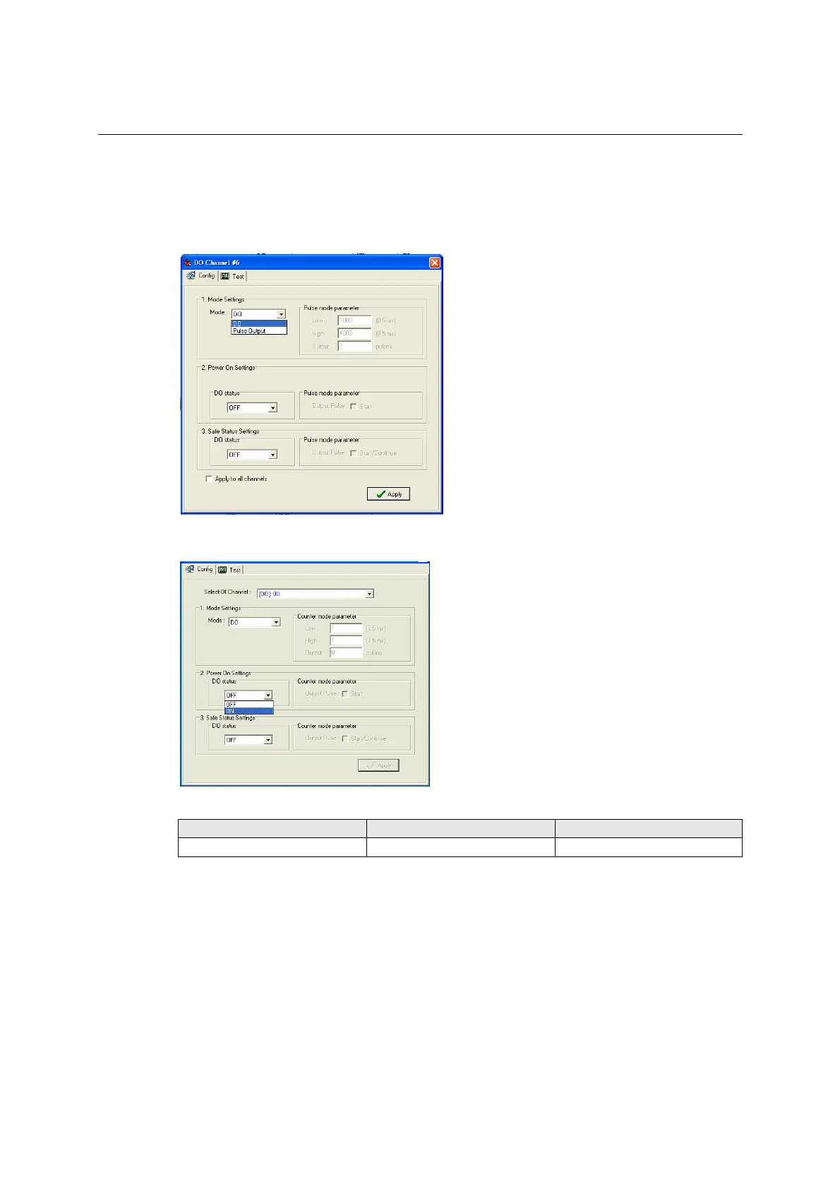
Configuring Digital Output Channels
The ioLogik E2210 is equipped with 8 DO (digital output or sink) channels that can be set individually
to “DO” or “Pulse Output” mode.
In DO mode, the specification is as follows.
Type Logic 0 (OFF) Logic 1 (ON)
DO mode Open Short
In Pulse Output mode, the selected digital output channel will generate a square wave as specified in the
pulse mode parameters. The low and high level widths are entered in multiples of 0.5ms, with a maximum
setting of 65,535 (32,767 ms).To set the low level width for 500 ms, you would enter 1000 (because 1000
x 0.5 ms = 500 ms). If the low width value is 5000 and the high width value is 5000, the pulse output
would be a square wave with a 5-second pulse cycle. If continuous pulse output is desired, enter “0” for
the number of pulses, otherwise enter the desired number of pulses between 1 and 4,294,967,295.