OnCell G3100 Series Getting Started
Wiring Requirements
Be sure to disconnect the power cord before installing and/or wiring your device. The OnCell
G3100 should be
secured at one location.
Calculate the maximum possible current in each power wire an
d common wire. Observe all
electrical codes
dictating the maximum current allowable for each wire size. If the current goes
above the maximum ratings,
the wiring could overheat, causing serious damage to your equipment.
handling the device. When plugged in, the device’s internal components
generate heat, and
consequently the casing may feel hot to the touch.
You should also follow the guidelines below:
• Use separate paths to route wiring for power and devices. If power wiring and device wiring paths must
cross, make sure the wires are perpendicular at the intersection point.
NOTE: Do not run signal or communication wiring and power wiring in the same wire conduit. To
avoid interference, wires with different signal characteristics should be routed separately.
• Use the type of signal transmitted through a wire to determine which wires should be kept separate. The
rule of thumb is that wiring that shares similar electrical characteristics can be bundled together.
• Keep input wiring and output wiring separate.
• Where necessary, it is advisable to label the wiring to all devices in the system.
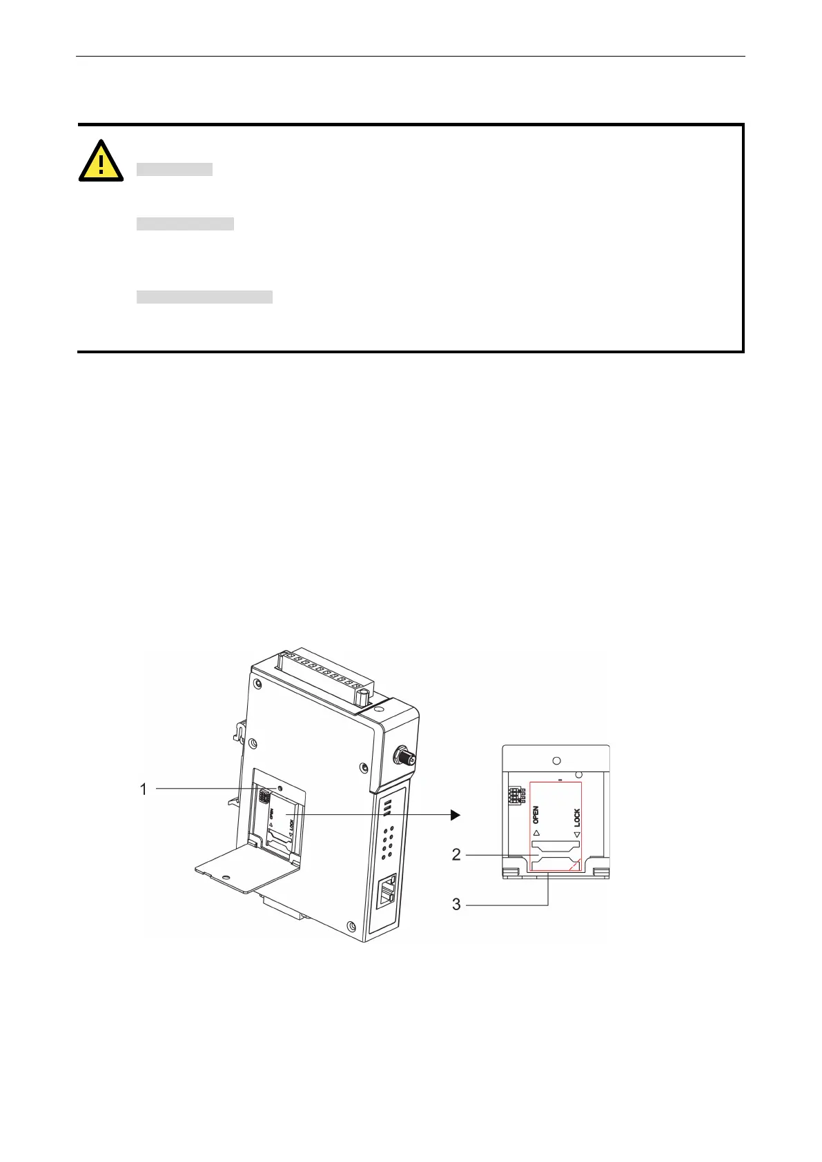
SIM Card Installation
In order to protect the SIM card, the SIM card slot is located inside the OnCell G3100’s casing. You will need to
unscrew and remove the outer SIM card cover before installing or removing the SIM card.
Follow these steps to remove or install the SIM card:
1. Remove the screw holding the outer SIM card cover.
2. Push the outer SIM card cover to the left to remove it.
3. Rotate it upwards to expose the SIM card slot.
(a) Remove the SIM card from the SIM card slot, or
(b) Insert a SIM card into the SIM card slot.
4. Reverse the above steps to replace the outer SIM card cover.
 Loading...