Confidential and proprietary information of NCRCorporation.
Unauthorized use, reproduction and/or distribution is strictly prohibited.
73
I/OBoard Connector Pinouts
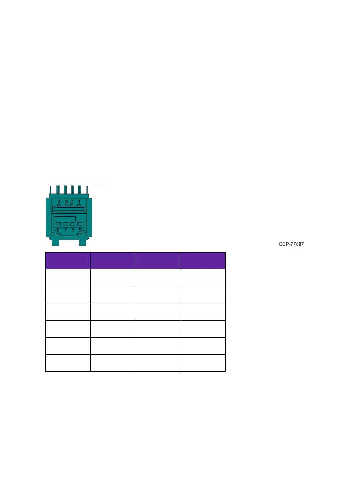
12V USB +Power
The I/O Board provides latching 12V Powered USB port (Foxconn P/N UB11123-GHT2-4F
or NCR approved equivalent). The 12V Powered USB port is capable of supplying 12V at
2.0A max. The color of the connector is teal.
The 12V of each port is fused with a self-healing poly-fuse (Polytronics Everfuse P/N
SMD2920P300TF/15 or NCR approved equivalent). An overcurrent signal is used to
detect when this fuse is open. This signal is connected to a GPIO on the Super I/O.
Current limiting power switches are provided on the 5V VBUS pins with a limit current of
1A.
The USBCentric I/O Board provides three 12V Powered USB ports, while the Serial
Centric I/O Board provides one 12V Powered USB port.
Signal Name Pin Pin Signal Name
USBPWR 1 5 GND
USB D– 2 6 +12V
USBD+ 3 7 +12V
GND 4 8 GND
FRAME GND 9 10 FRAME GND
FRAME GND 11 12 FRAME GND
24V USB +Power
The I/O Board provides one latching 24V Powered USB port (Foxconn P/N UB11123-
GHR3-4F or NCR approved equivalent). The 24V Powered USB port is capable of
supplying 24V at 2.3A continuous and 3.0A peak. The color of the connector is red.
 Loading...