148
CHAPTER 6 PORT FUNCTIONS
P-ch
WR
PM
WR
PORT
RD
WR
PUO
V
DD
Selector
PUO12
Output Latch
(P120 to P127)
PM120-PM127
Internal bus
P120/RTP0
P127/RTP7
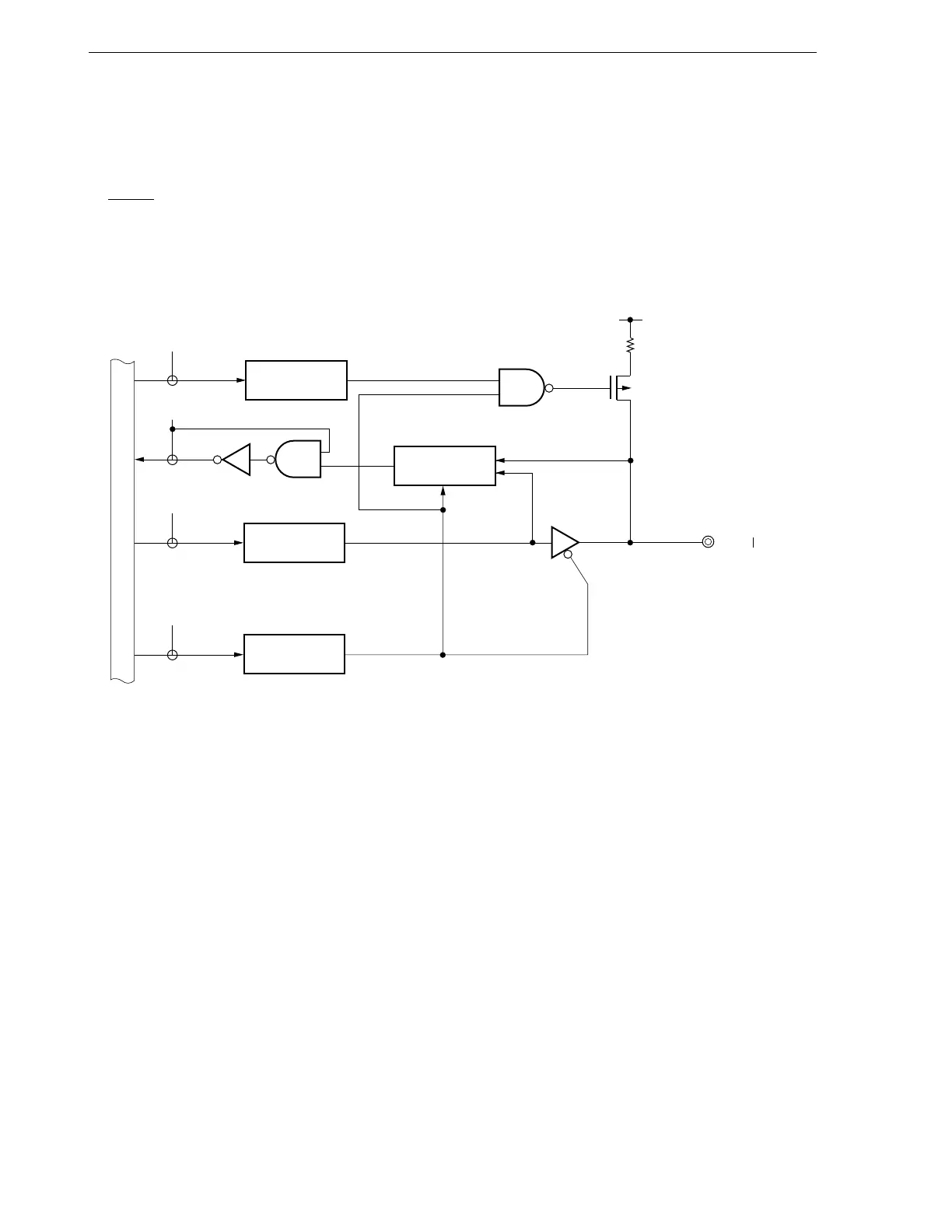
6.2.10 Port 12
This is an 8-bit input/output port with output latches. Input mode/output mode can be specified bit-wise by means
of port mode register 12 (PM12). When pins P120 to P127 are used as input port pins, an on-chip pull-up resistor
can be used as an 8-bit unit by means of pull-up resistor option register H (PUOH).
Alternate function includes real-time output.
RESET input sets the input mode.
Figure 6-17 shows a block diagram of port 12.
Figure 6-17. P120 to P127 Block Diagram
PUO : Pull-up resistor option register
PM : Port mode register
RD : Port 12 read signal
WR : Port 12 write signal