8.5 Performance test
FRA5087
8.5.9 Analyzer measuring error frequency response
Frequency dependence of the CH1/CH2 measurement value at 10 mVpeak output is tested.
a) Setting
FRA5087 oscillator FRA5087 analyzer
Sweep upper limit frequency 10 MHz Integration 50 cycles
Sweep lower limit frequency 10 Hz Measuring mode CH1, CH2
Output waveform Sinewave Analyzing mode CH1/CH2
Output voltage Display mode X axis : logF
AC 10 mVpeak Y1 axis : dBR
DC bias 0 V X2 axis :
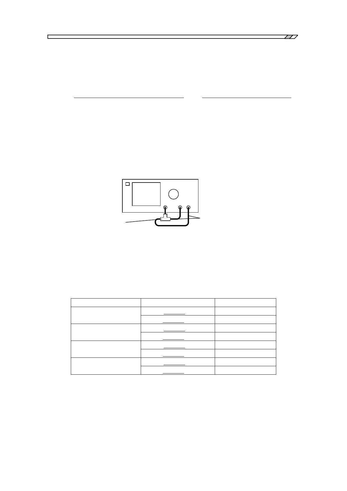
b) Connection
FRA5087
BNC-BNC
coaxial cables
BNC
T-type divider
OSC CH1 CH2
c) Procedure
Use FRA5087 for sweep measurement.
Read the absolute maximum measured results for dBR and θ for frequency ranges up to 20
kHz, 500 kHz, 2.2 MHz and 10 MHz from the LCD screen.
d) Judgment