3.4 Insulation breakdown voltages of input and output voltages
FRA5087
3.4 Insulation breakdown voltages of input and output voltages
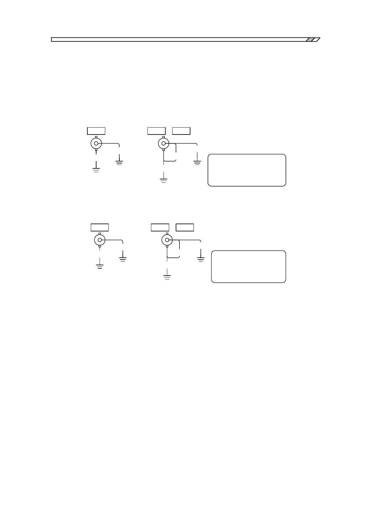
The oscillator output terminal (OSC) and the analyzer input terminals (CH1 and CH2)
individually are electrically insulated from the cabinet. The minimum dielectric breakdown
voltage between the cabinet and the above mentioned parts of the FRA5087 is 250 Vrms. (CAT I)
when the accompanying BNC cable is used, and 30 Vrms when another cable is used. Be careful
not to apply voltages exceeding 250 Vrms between the cabinet and the individual polarities (i.e.,
signals and ground) of OSC, CH1 and CH2 terminals.
OSC CH1 CH2、
*1:
250 Vrms (AC), or ±
200V (DC), alternatively ±
350 Vpeak (AC + DC)
250Vrms
250Vrms
250Vrms
250Vrms
Measurement
category I
250Vrms
*1
Measurement
category I
Fig. 3-1 From-enclosure isolation voltage specifications (when accompanying BNC
cable is used)
OSC CH1 CH2、
*2:
30 Vrms (AC), or ±60V
(DC), alternatively ±42
Vpeak (AC + DC)
30Vrms
30Vrms
30Vrms
30Vrms
30Vrms
*2
Measurement
category I
Measurement
category I
Fig. 3-2 From-enclosure isolation voltage specifications (when a cable other than
the accompanying cable is used)
OSC, CH1 and CH2 are electrically insulated to each other. The minimum insulation breakdown
voltage between the signal and the ground polarities for OSC, CH1 and CH2, individually, is 250
Vrms. (CAT I) when the accompanying BNC cable is used, and 30 Vrms when another cable is
used. The same minimum insulation breakdown voltage of 250 Vrms applies between signal
polarities of OSC, CH1 and CH2.