5.4 Operation method
FRA5087
5.4 Operation method
5.4.1 Impedance display description
The function displays impedance, resistance, reactance, conductance and susceptance with linear
and logarithmic graphs.
In units setting for the impedance and analysis modes CH1/CH2 or CH2/CH1, axis data R, A and
B have the following meanings.
R: Impedance (CH1/CH2) or admittance (CH2/CH1)
A: Resistance (CH1/CH2) or conductance (CH2/CH1)
B: Reactance (CH1/CH2) or susceptance (CH2/CH1)
When impedance is displayed, CH1 is fixed to voltage input and CH2 fixed to current input.
To allow 0.01 m to 1 k shunt resistance to be used for current to voltage conversion,
[WEIGHTING FACTOR] by the menu [Input] setting range is 0 to 1.0E+6 (resolution 5 digits or
0.1E-09).
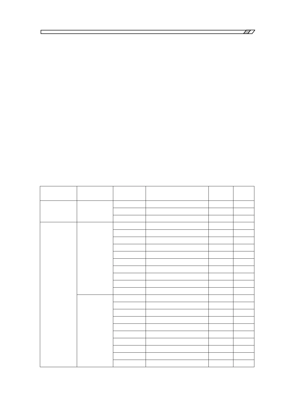
Table 5-1 indicates graph axis contents, scale and units with respect to units, analyze mode and
display mode settings.
Table 5-1 Graph axis contents
CH1/CH2,
CH2/CH1,
CH1,CH2