4.6 Display setting
FRA5087
OSC: 2.2000000000MHz 7.00 Vpeak DC 1.00 V INTEG: 100cycle HMNC: 1
SWP: 100steps/sweep CPRSN:OFF SLSWP:OFF ANAL:CH2/CH1 EQL:OFF
SWEEP STOP
1
2
3
4
5
6
PHASE[deg]
FREQUENCY(Hz)
GAIN[dB]
1k 10k 100k 1M
-20m
-10m
0
m
10m
20m
30m
40m
50m
60m
1k 10k 100k 1M
-0.08
-0.07
-0.06
-0.05
-0.04
-0.03
-0.02
-0.01
0
*f: 2.2000000000MHz *R: 0.038 dB *θ : -0.06 deg
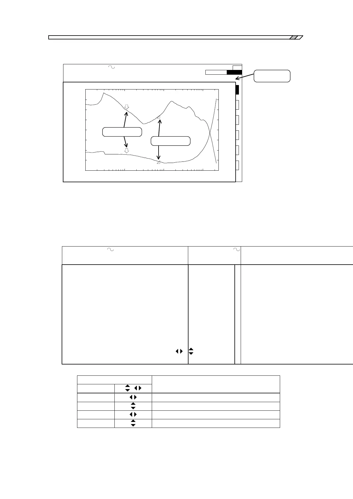
Normal marker
Data display
portion
*
*
Delta marker
Fig. 4-10 Data marker display
When markers are displayed in the screen, a mark of “*” is attached just before the displayed
item (e.g., f, R, , etc.), which is to indicate the value is the one read out by the marker. The
mark “*” is not displayed when frequency seep measurements are being done (See Fig. 4-11
data display examples).
OSC: 2.2000000000MHz 7.00 Vpeak DC 1.00 V INTEG: 100cycle HMNC: 1
SWP: 100steps/sweep CPRSN:OFF SLSWP:OFF ANAL:CH2/CH1 EQL:OFF
*f: 2.2000000000MHz *R: 0.038 dB *θ : -0.06 deg
OSC: 2.2000000000MHz 7.00 Vpeak DC 1.00 V INTEG: 100cycle HMNC: 1
SWP: 100steps/sweep CPRSN:OFF SLSWP:OFF ANAL:CH2/CH1 EQL:OFF
f: 2.2000000000MHz R: 0.038 dB θ : -0.06 deg
During marker being displayed During frequency sweep measurement
Fig. 4-11 Examples of data display
b) How to use line markers
Line markers are displayed in two forms; one is a straight line parallel to the x axis (i.e., y
axis marker) and the other is a straight line parallel to the y axis (i.e., x axis marker). There
are, again, two types of markers for each form of markers: normal markers and delta markers.
The normal marker is displayed in solid line and the delta marker is displayed in broken line.
The table below shows which line markers are active under certain combination of lamp
status (lamps referred here are those of
,
and SET.). Active markers are those
which move by knob actions.
Table 4-3 Active line markers