4.7 Equalization
FRA5087
4.7.2 Principle of equalization
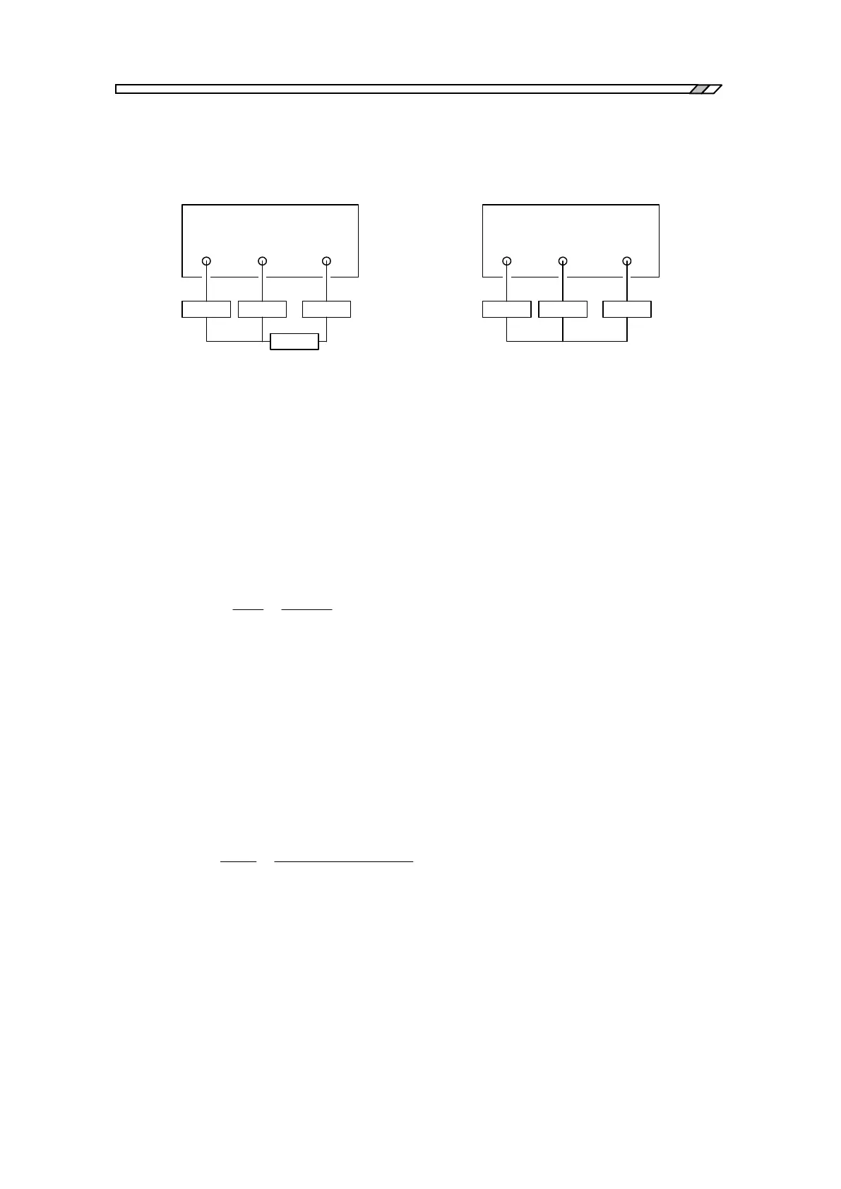
The equalization principle is described below with respect to Fig. 4-14.
OSC CH1 CH2
FRA5087
Amp Probe1 Probe2
Fdut
Vin Vout
V1m V2m
OSC CH1 CH2
FRA5087
Amp Probe1 Probe2
Veql
V1e V2e
a) Measurement of DUT b) Measurement of measurement system
Fig. 4-14 Principle of equalization
1) Measure by using the connection shown in Fig. 4-14b. Set the Amp output voltage level
at Veql to have CH1 and CH2 input voltage levels, V1e and V2e, respectively, to be the
following:
V1e = Veql Probe1
V2e = Veql Probe2
2) Record/store the measured data above in the EQL memory as the equalization data. The
data for CH2/CH1 are recorded/stored in the EQL memory. Therefore, the content of the
EQL memory will be as follows:
3) Connect as shown in Fig. 4-14a and measure the overall dut system. Putting the Amp
output voltage to be Vin and the Fdut output voltage to be Vout, you can obtain input
voltages of CH1 and CH2, V1m and V2m, respectively, as follows:
V1m = Vin Probe1
V2m = Vout Probe2 = Vin Fdut Probe2
4) Equalize these data by using the data stored in the EQL memory. Since the actual
processing of equalization comprises division operations, i.e., the CH2 measurement value
divided by the value stored in the EQL memory, CH1 and CH2 voltage levels after
equalization, V1 and V2, respectively, will be as follows:
V1 V1m Vin Probe1
V2 =
V2m
EQL
Vin Fdut Probe2
Probe2 / Probe1
Vin Fdut Probe1
5) Display the ratio of CH1 to CH2 (i.e., ratio of V1 to V2) to cancel the effects of Vin and
Probe1. The displayed data show Fdut, the characteristics of the DUT (device under test).
Note, however, that the effect of Probe1 will be left unremoved, if the absolute value of
CH1 or CH2 is displayed.