3.2 Input and output connections
WF1946B
3-9
Trigger/sweep input (TRIG/SWEEP IN)
Signal characteristics: The following types are produced during the burst oscillation mode.
Trigger; Select oscillation start for either
or .
Gate ; Select oscillation at either high or low level.
Triggered gate: Oscillation start/stop at
or . Select either.
Minimum pulse width is 50 ns.
In sweep oscillation mode, the sweep starts at
or . Select either.
Minimum pulse width is 200 ns.
Input voltage : High level ≥ +3.9 V
Low level ≤ +1.6 V
Input voltage range : −0.5 to +5.5 V
Input impedance : Pull up to +5 V at approx. 10 kΩ
Ground : Connected to chassis ground
Do not apply a signal exceeding the above input voltage range. The unit can be damaged.
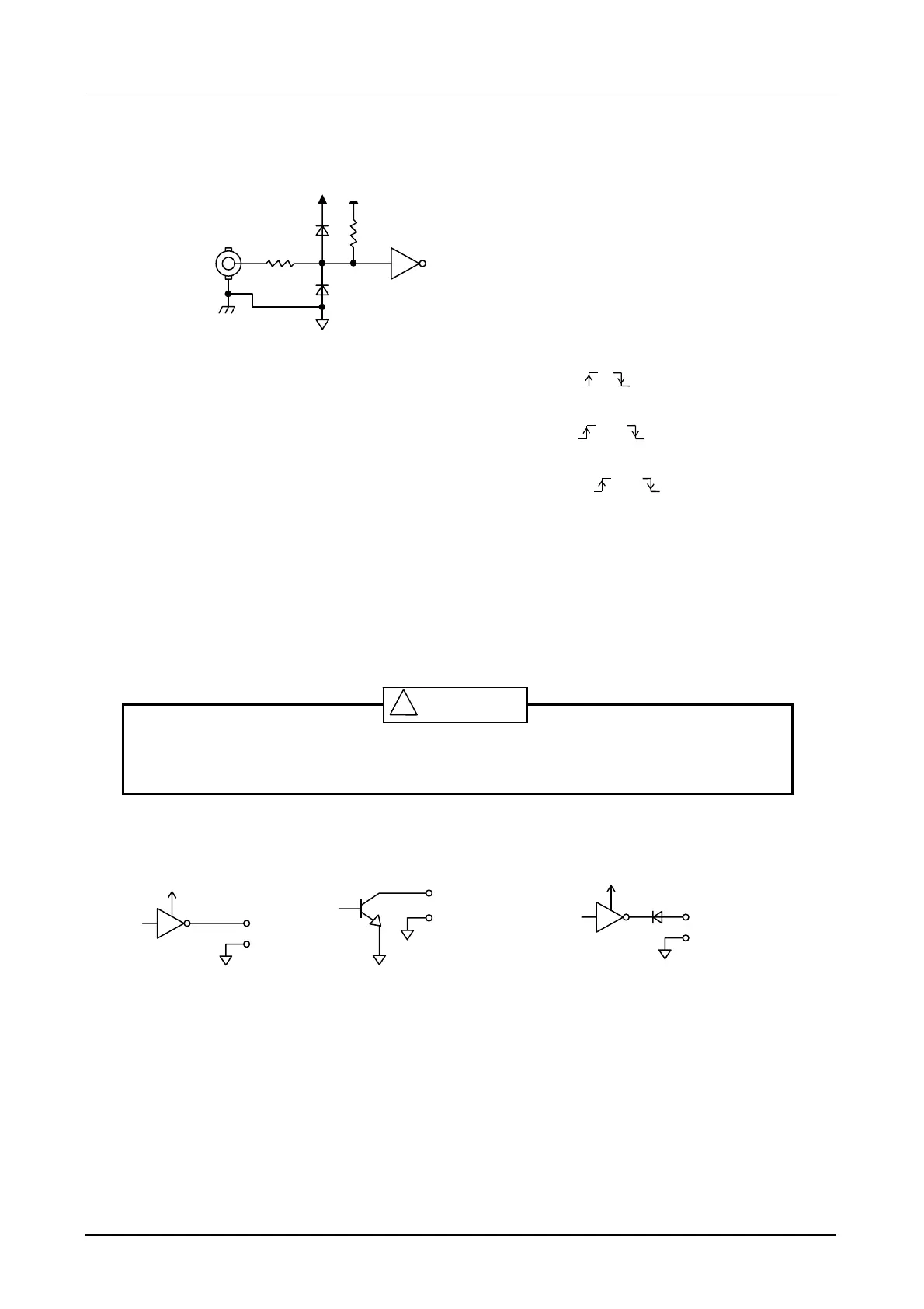
• Drive circuit examples
Connect the trigger and sweep input drive signals to TTL or C-MOS logic IC outputs.
Since the input circuit is provided with a built-in pullup resistor, an open collector output drive can also be
used. However, contact chatter from a mechanical switch or relay can prevent normal operation. Also,
chattering will prevent normal operation when the oscillation mode is triggered gate.
Avoid using a logic IC circuit having a power supply voltage higher than +5 V such as example (c) for the
WF1946B input
! CAUTION
+5 V
+12 V~
(a) TTL logic output (b) Open collector output (c) High voltage logic output
TRIG/SWEEP IN
+5 V
10 kΩ
100 Ω
+5 V
D