3.2 Input and output connections
WF1946B
3-14
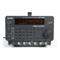
Digital output (DIGITAL OUT)
(1992A option)
Output impedance : Approx. 115 Ω
Output voltage : 0 V/+5 V (open)
Connections : See table
Ground : Signal GND lines connected to signal ground (floating from chassis)
Drain line connected to chassis ground
Connect GND to all target signal grounds. Lease unused signal lines open.
When the drain line is connected to the target signal ground, the WF1946B signal grounds (FUNCTION
OUT, SYNC OUT, EXT ADD IN, EXT AM IN) are grounded to chassis.
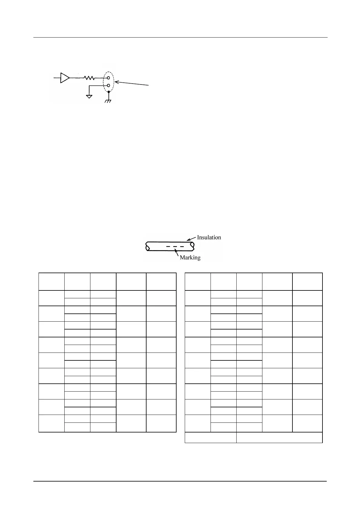
The accessory cable signals are indicated by marking quantity and color, and insulation color.
Signal
Connec-t
ion
Mark
color
Mark
quantity
Insulation
color
Signal
Connec-t
ion
Mark
color
Mark
quantity
Insulation
color
Signal Red Signal Red
Output
control
GND Black
3 White D07
GND Black
2 White
Signal Red Signal Red
D15
(MSB)
GND Black
2 Orange D06
GND Black
4 Orange
Signal Red Signal Red
D14
GND Black
3 Yellow D05
GND Black
1 White
Signal Red Signal Red
D13
GND Black
1 Pink D04
GND Black
3 gray
Signal Red Signal Red
D12
GND Black
2 Pink D03
GND Black
2 gray
Signal Red Signal Red
D11
GND Black
2 Yellow D02
GND Black
4 gray
Signal Red Signal Red
D10
GND Black
3 Pink
D01
(LSB)
GND Black
1 gray
Signal Red Signal Red
D09
GND Black
1 Yellow Clock
GND Black
4 White
Signal Red Signal Red
D08
GND Black
3 Orange
Not
used
GND Black
1 Orange
Chassis ground Drain line
•
The output control line is pulled up to +5 V at approx. 10 kΩ. When this line is low level, the clock and
D01 to D15 output signals are on. When open, the output signals are high impedance.
DIGITAL OUT connector’s housing and drain line of the cable.
100Ω
Note: GND: Signal ground