Troubleshooting
6-16 Manual # 42-02-1P28 A3
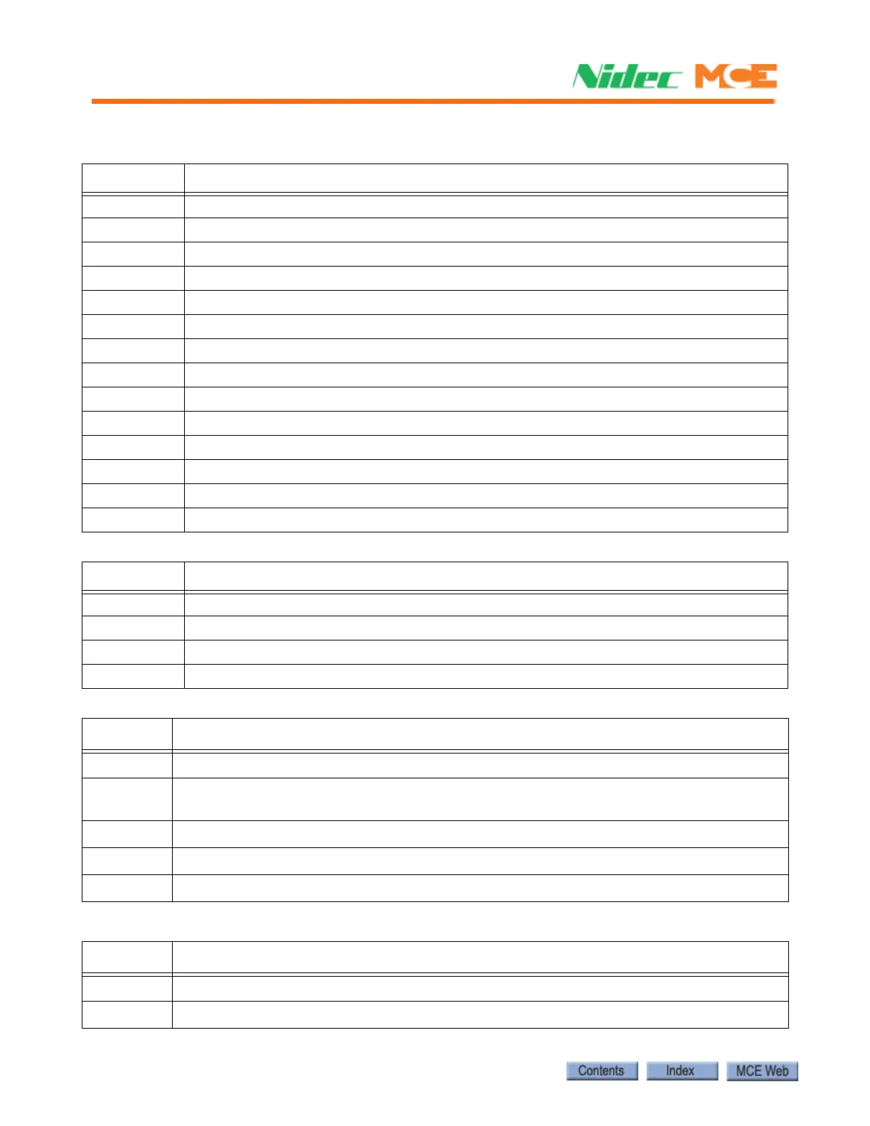
Table 6.11 HC-MPU-2-TS Board Indicators
Indicators Description
CPU A ON CPU A is executing its program
CPU B ON CPU B is executing its program
LED1 Reserved
LED2 Reserved
FAULT A fault has been detected.
CPU ON All processors are fully functional.
MLT Motor/Valve Limit Timer: The motor/valve limit timer has elapsed.
TOS Timed Out of Service: The TOS timer has elapsed and the car is out of service.
FIRE Fire Service: The car is on fire service operation.
INSP Inspection: The car is on inspection operation.
IND Independent Service: The car is on independent service.
HS High Speed: The car is running at high speed.
DLK Doors Locked: The door lock contacts are made.
SAF ON Safety On: The safety circuit is made.
Table 6.12 HC-MPU-2-TS Board Test Points
Test Points Description
GND 0V
+3.3V +3.3 Vdc measured between this test point and TP GND.
+5V +5 Vdc measured between this test point and TP GND.
+25V unregulated 25Vdc from the HC-CHP board
Table 6.13 HC-MPU-2-TS Board Terminals
Connector Description
J2 Used to program CPU A. IDC connector.
J4
External CAN Port. Three pin Weidmuller connector (CAN H, CAN L, SHLD). Signal for CAN
connections outside the controller cabinet.
J3 Internal CAN Port. RJ12 connector/cable to the HC-CHP CAN Hub / Power Supply board.
J5 Used to program CPU B. Twenty pin header connector.
J9 Low voltage AC input (16V). Two pin IDC connector.
Table 6.14 HC-MPU-2-TS Board Switches
Switch Description
S1 RSTA: Reset CPU A
S2 RSTB: Reset CPU B