Troubleshooting
6-26 Manual # 42-02-1P28 A3
ICE-COP-2 Board Details
• 24V Inputs Only: Typical circuit for terminals I1 through I16.
• 24V Outputs Only: Typical circuits for terminals O1 through O16.
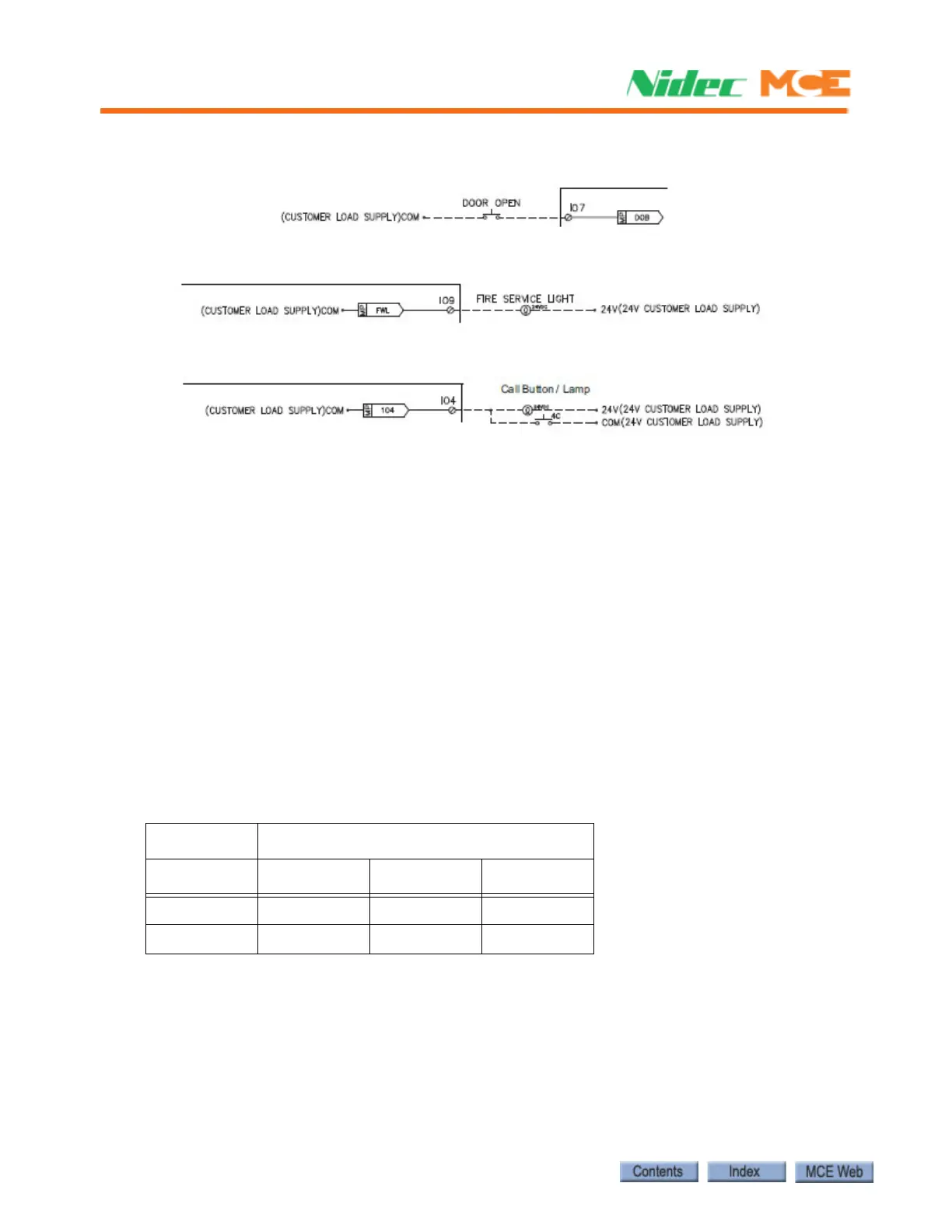
• 24V Inputs and Outputs Only: Typical circuit for terminals IO1 through IO16.
S2 Switches Eight-position DIP switch S2 allows a unique address to be set for each
COP board, places the board in CAN or iControl communication mode, sets the board input
threshold, and determines the CAN baud rate (when CAN is enabled).
• RS485 or CAN Communication
• For Motion controls, the board must be set to use CAN communication.
• CAN Enable: Verify/set switch 8 to the ON position.
• Motion Input Threshold Detection
On COP-2 boards with software version 1.1 or later, the input threshold level may be set to
900 or 700mV using DIP switch rocker 5.
• Board revision X2-1 or greater: Recommended rocker 5 OFF: 900mV (default)
• Board revision X2-0: Recommended, rocker 5 ON: 700mV
• Motion Board Addressing
For Motion control, each COP-2 board used must have a unique address.
• Addressing - switches 1, 2, and 3:
S2 SPARE I/O COP BOARDS
Board SW1 SW2 SW3
4 ONONOFF
8 ONONON