Operating & Maintaining the Eden 3-D Printer
7–24
DOC-00500 Rev. F
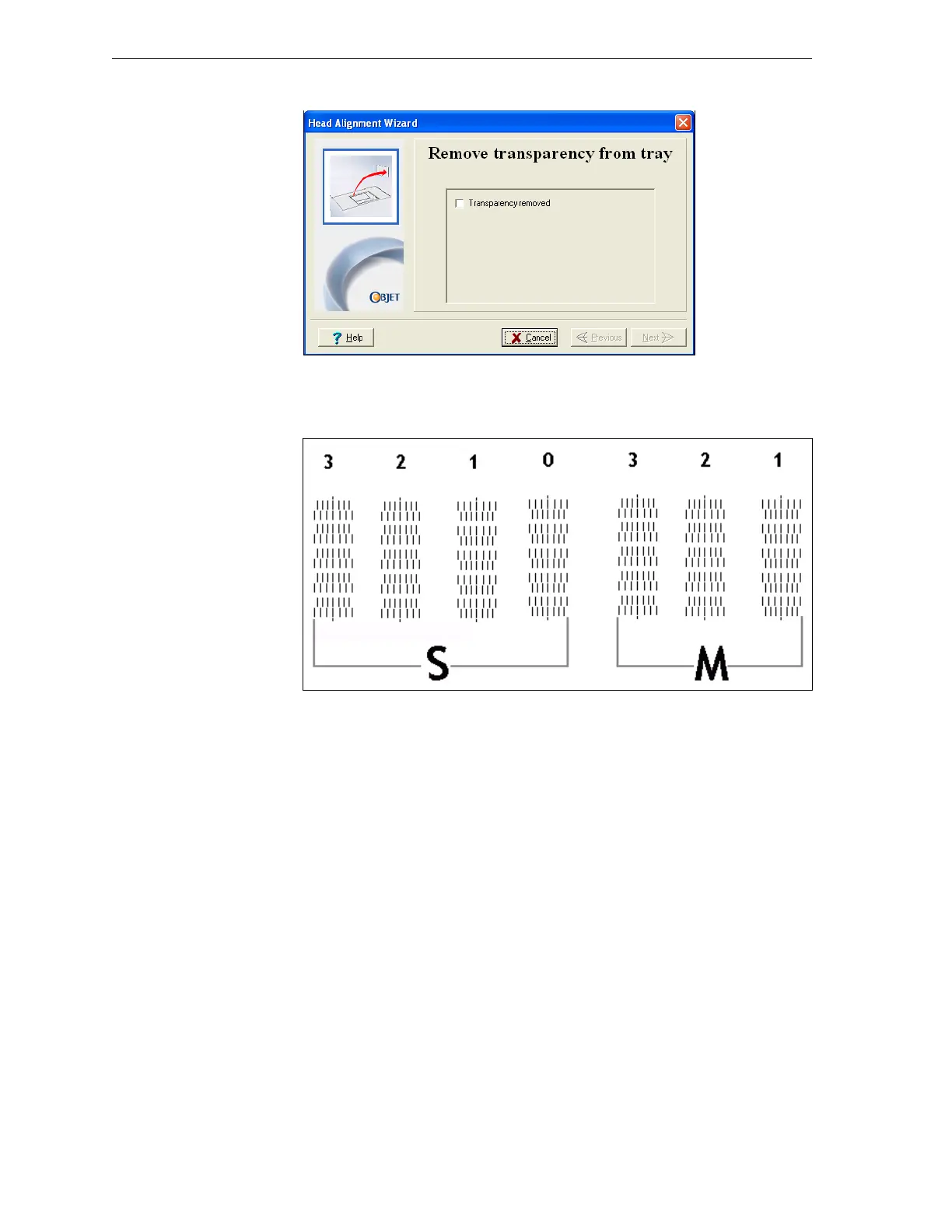
8. Whenthefollowingscreenappears,removethetransparency.
Figure 7-29: Head Alignment wizard—steps 8–10
Thetransparencysheetisprintedwithsetsofverticallinesinseven
columns,eachshowingtheresultsfromadifferentprinthead.
Figure 7-30: Sample head-alignment test
• Thethreecolumnsontherightwereprintedbytheheadsusedfor
applyingmodelmaterialwhenproducingmodels.Fromrightto
left,thecolumnsrepresentheadsM1,M2,M3,respectively.(There
isnocolumnforheadM0becauseitsalignmentisusedasa
referenceforaligningallotherheads.)
• Thefourcolumnsoflinesontheleftwereprintedbytheheadsused
forapplyingsupportmaterial.ThecolumnsrepresentheadsS3,S2,
S1andS0,respectively.