DOC-00500 Rev. F 7–25
Eden500V/350V/350 User Guide
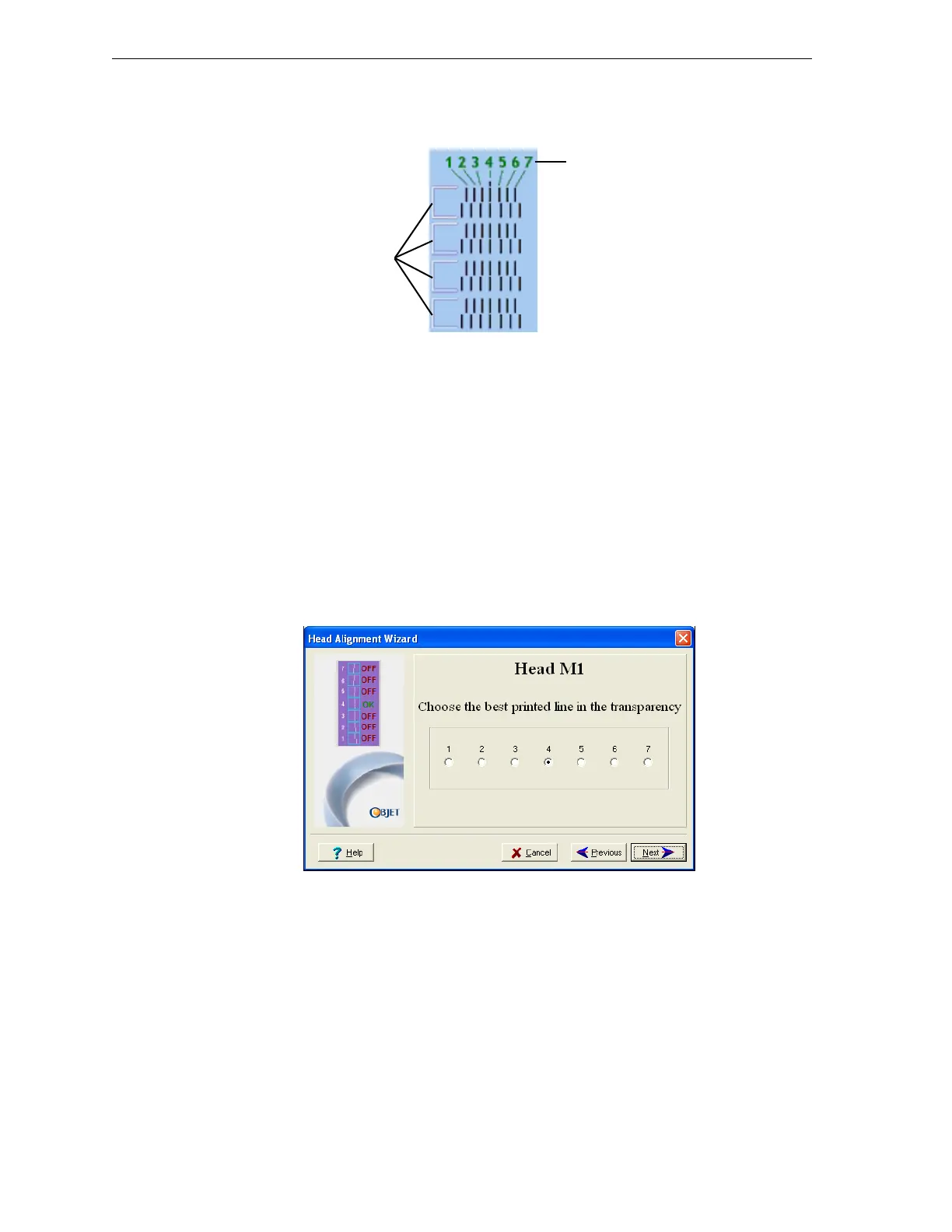
9. Foreachcolumnoflines,useamagnifyingglassorloupetoinspect
pairsofconsecutiverowsprintedonthetransparencytoseewherethe
verticallinesalign.
Figure 7-31: Comparing rows of alignment lines
Note: It does not matter which pair of lines you inspect, since they were all
printed by the same head. Choose a pair of clearly printed lines for the
inspection. (Since some nozzles may not print clearly, you may have to
inspect several pairs of lines to properly inspect the alignment.)
Optimumheadalignmentisshownwhenthefourthlinesintheupper
andlowerrowsarealigned,asinfigure 7‐31.Intheexampleshown,no
changetotheheadalignmentisnecessary.Ifotherlinesinthesetare
aligned,youneedtochangethealignmentofthathead—inthe
next
wizardscreens.
10. Inthewizardscreenshowninfigure 7‐29,selecttheTransparency
removedcheckbox,andclick
Next.
Thefirstinaseriesofalignmentscreensappears.
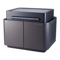
Figure 7-32: Head alignment screen
11. Inthehead‐alignmentscreen,selectthenumberthatindicateswhich
linesalignintheupperandlowerrowsofapaironthetransparency
(countingfromtheleft)forthisprinthead.
Note: Because the alignment of the fourth lines is optimum, the number “4”
is selected, by default, in the wizard screen. This does not change the head
alignment. If you select other numbers, the wizard adjusts the head
alignment, accordingly.
12. ClickNexttodisplaythenextheadalignmentscreen,andagainselect
thenumberrepresentingthemostcloselyalignedverticallinesonthe
transparencyforthatprinthead.
Alignment-line
numbering, left-to-right
Row pairs