Input Channels 1 and 2 can accept:
• Analog input voltages (1-5 VDC)
• Current inputs (4-20mA) converted to 1-5 VDC by installing the 4-20 jumper
• Low level RTD input signals (0.20–0.55 VDC)
Installing the RTD jumper increases the signal input by a factor of 10X.
Input Channels 3 and 4 can accept:
• Analog input voltages (1-5 VDC)
• Current inputs (4-20mA) converted to 1-5 VDC by installing the 4-20 jumper
• Pulse signals (0-12 kHz) by removing the four “A” jumpers and installing the two “P” jumpers
Input Channel 4 can be configured for AC or DC signal coupling. The input signal trigger
threshold can be lowered from 3.5 to 1.5 VDC by removing the input threshold HI jumper, which
makes it suitable for interfacing to Solartron type densitometers.
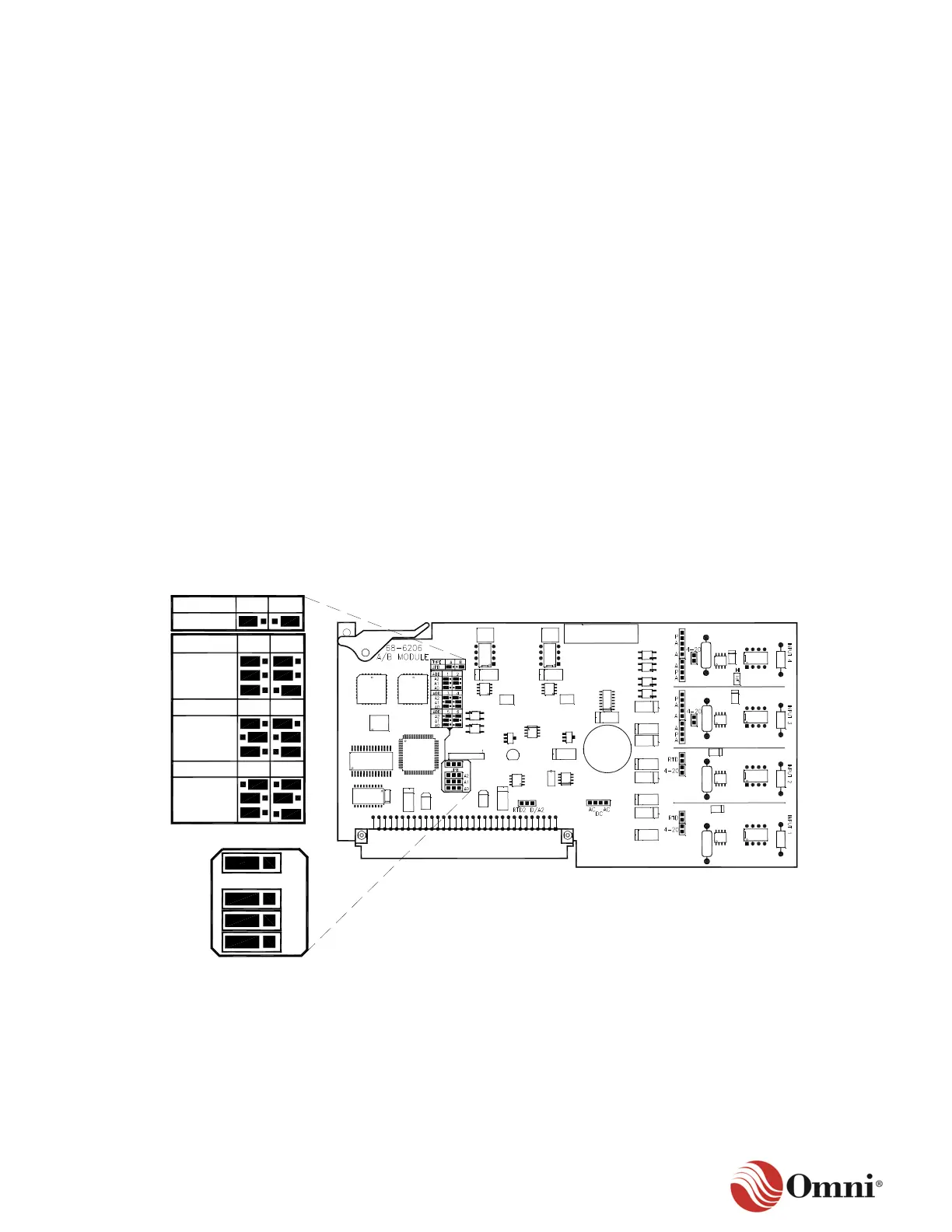
A.3 A/B Module Setup
Configure the A/B Combo as either an A module or a B module by positioning the TYPE jumper
(JPB) as indicated in Figure A-1.
Assign a unique address to each A or B module installed into the OMNI flow computer by
positioning the jumper’s address (ADD) in the jumper table as indicated in Figure A-1.
Figure A-1: A Module Type and Address Jumpers
 Loading...