5 Installation
5-30
CJ2 CPU Unit Hardware User’s Manual
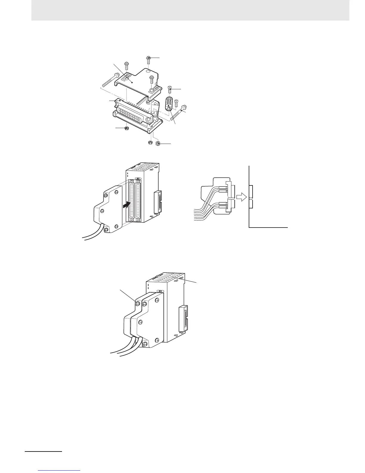
4. Assemble the connector (purchased separately).
5. Insert the wired connector.
6. Remove the protective label after wiring has been completed to allow air circulation needed for
cooling.
Tighten the connector lock screws to a torque of 0.2 N·m.
Connector cover
Small screws (3)
Socket
Nuts (3)
Small screws (2)
Connector lock
screws
Cable bracket
Nuts (2)
0 1 2 3 4 5 6 7
8 9
12 13
14
15
10 11
0 1 2 3 4 5 6 7
8 9
12
13 14
15
10 11
I
II
ID261
Connector
Connector
Basic I/O Unit
Basic I/O Unit
0
1
2
3
4
5
6
7
8
9
12 13
14 1
5
10
11
0 1
2
3
4
5 6
7
8
9
1
2
13
14
15
10 1
1
I
II
ID261
After wiring
Remove label after wiring.
Connector lock screws