5-29
5 Installation
CJ2 CPU Unit Hardware User’s Manual
5-3 Wiring
5
5-3-3 Wiring Basic I/O Units with Connectors
z Wire Size
We recommend using cable with wire gauges of AWG 24 or AWG 28 (0.2 mm
2
to 0.08 mm
2
). Use
cable with external wire diameters of 1.61 mm max.
z Wiring Procedure
The following wiring procedure is an example for Fujitsu-compatible connectors.
1. Check that each Unit is installed securely.
Precautions for Correct UsePrecautions for Correct Use
Do not force the cables.
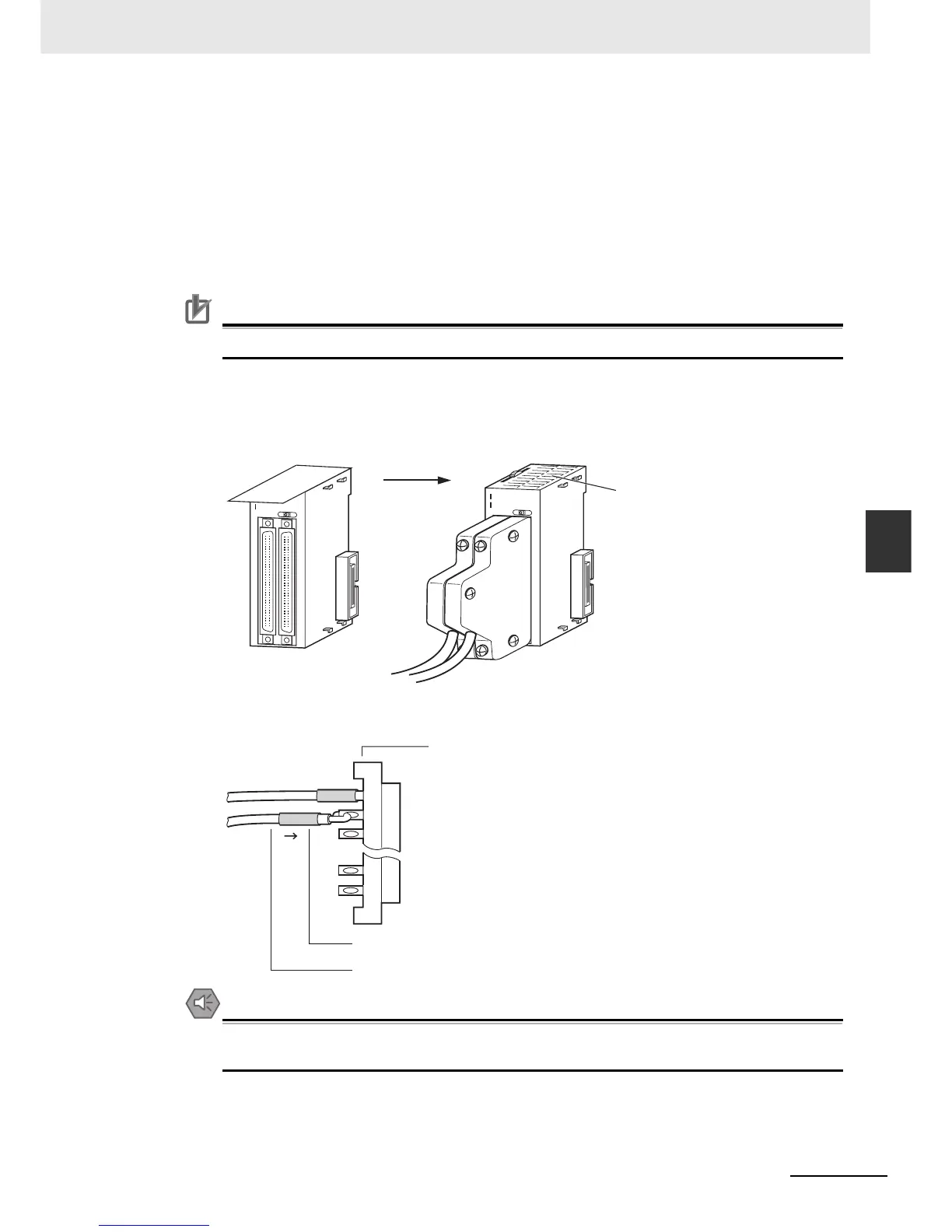
2. Do not remove the protective label from the top of the Unit until wiring has been completed. This
label prevents wire strands and other foreign matter from entering the Unit during wiring.
(Remove the label after wiring has been completed to allow air circulation needed for cooling.)
3. When solder-type connectors are being used, be sure not to accidentally short adjacent termi-
nals. Cover the solder joint with heat-shrink tubing.
Precautions for Safe Use
Double-check to make sure that the Output Unit's power supply leads have not been reversed. If
the leads are reversed, the Unit's internal fuse will blow and the Unit will not operate.
0
1
2
3
4
5
6
7
8
9
1
2
1
314
15
1
0
1
1
0
1
2
3
4
5
6
7
8
9
12
1
31
4
15
10 11
I
II
ID261
0
1
2
3
4
5
6
7
8
9
1
2
1
3
1
4
15
10
11
0
1
2
3
4
5
6
7
8
9
12
13 1
4
15
10 11
I
II
ID261
Before wiring
After wiring
Remove label
after wiring
Solder-type connector
Heat-shrink tubing
Wire (0.2 to 0.13 mm
2
)