5-43
5 Installation
CJ2 CPU Unit Hardware User’s Manual
5-4 Control Panel Installation
5
5-4-5 Electrical Environment
Observe the following points when wiring the power supply system.
• Separate the PLC power supply from the I/O device power supply and install a noise filter near the
PLC power supply feed section.
• Use an isolating transformer to significantly reduce noise between the PLC and the ground. Install
the isolating transformer between the PLC power supply and the noise filter, and do not ground the
secondary coil of the transformer.
• Keep the wiring between the transformer and the PLC as short as possible, twist the wires well, and
keep the wiring separate from high-voltage and power lines.
Observe the following points when wiring external I/O signal lines.
• To absorb reverse electromotive force when an inductive load is connected to an output signal, con-
nect a surge suppressor near the inductive load in an AC circuit, and connect a diode near the induc-
tive load in a DC circuit.
• Never bundle output signal lines with high-voltage or power lines, and do not route them in close
proximity or parallel to such lines. If output signal lines must be routed in close proximity to such lines,
place them in separate ducts or conduits and be sure to ground the ducts or conduits.
• If the signal lines and power lines cannot be routed in separate ducts, use shielded cable. Connect
the shield to the ground terminal at the PLC, and leave it unconnected at the input device.
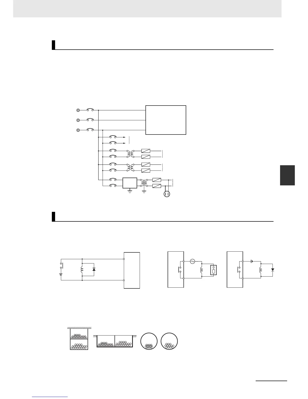
Wire Layout for the Power Supply System
Wiring External I/O Signal Lines
Power Supply System Diagram
Power circuits
Noise
filter
Power supply for general operations circuits
Power supply for PLC input circuits
Power supply for PLC output circuits
PLC power supply
Outlet (for peripheral devices)
Input Signal Noise Countermeasures
PLC
DC Input
Unit
Inductive
load
Diode
Connect a diode in a DC circuit.
Output Signal Noise Countermeasures
PLC
Output
Unit
PLC
Output
Unit
Connect a diode in a DC circuit.Connect a surge suppressor in an AC circuit.
Inductive
load
Inductive
load
I/O Cable Arrangement
Floor ducts Conduit
Suspended ducts
I/O cables
I/O cables
Power lines
Power lines
I/O cables Power lines