5 Installation
5-44
CJ2 CPU Unit Hardware User’s Manual
• Wire the lines so that common impedance does not occur. Such wiring will increase the number of
wires, so use common return circuits. Use thick wires with sufficient allowance for the return circuits,
and bundle them with lines of the same signal level.
• For long I/O lines, wire the input and output signal lines separately.
• Use twisted-pair wires for pilot lamps (and particularly lamps with filaments).
• Use countermeasures, such as CR surge absorbers and diodes, for input device and output load
device noise sources, as required.
Wiring, and noise countermeasures in particular, are based on experience, and it is necessary to
closely manage wiring based on experience and information in the manuals.
z Wiring Routes
Each of the following combinations include different signal types, properties, or levels. They will
cause the signal-to-noise ratio to drop due to factors such as electrical induction. As a general rule
when wiring, either use separate cables or separate wiring routes for these items. Future mainte-
nance operations and changes to the system will also be made easier by carefully organizing the
wiring from the start.
• Power lines and signal lines
• Input signals and output signals
• Analog signals and digital signals
• High-level signals and low-level signals
• Communications lines and power lines
• DC signals and AC signals
• High-frequency devices (such as Inverters) and signal lines (communications)
z Wiring Methods
Observe the following points when wiring power supply and signal cables.
• When routing signal cables with differing characteristics through the same duct, always keep them
separated.
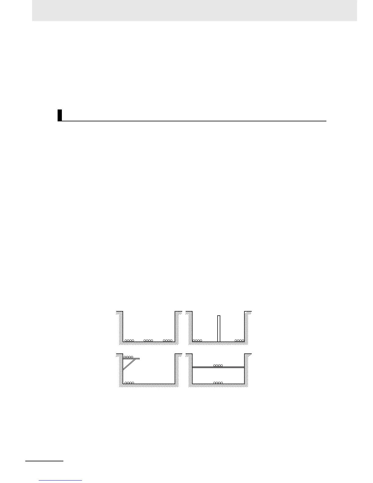
• As much as possible, avoid routing multiple power supply lines through the same duct. If it cannot
be avoided, then construct a partition between them in the duct and ground the partition.
External Wiring
Partitioning Methods for Signal and Power Supply Cables
(a) (b)
(c) (d)
Signal cables
Signal cables
Signal cables
Power supply cables
Power supply cables
Partition
Signal
cables
(A)
Signal
cables (B)
Signal
cables
(C)
Power
supply
cables