Appendices
A-94
CJ2 CPU Unit Hardware User’s Manual
• The table of fatal errors is arranged in ascending order of error codes.
• When two or more errors occur at the same time, the error code of the more serious error will be
recorded in A400.
• If the IOM Hold Bit hasn't been turned ON to protect I/O memory, all nonretained areas of I/O memory
will be cleared when a fatal error other than FALS(007) occurs.
• If the IOM Hold Bit is ON, the contents of I/O memory will be retained but all outputs will be turned OFF.
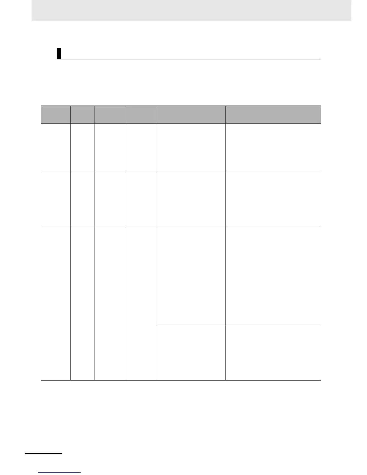
Table of Fatal Errors
Error
Error
code
(inA400)
Error flag
(Auxiliary
Area)
Flag and
word data
Probable cause Possible remedy
Cycle Time
Error
0x809F A401.08: Cycle
Time Too Long
Flag
--- The cycle time has exceeded the
maximum cycle time (watch cycle
time) set in the PLC Setup.
Change the program to reduce the cycle time or
change the maximum cycle time setting. Check the
Maximum Interrupt Task Processing Time in A440
and see if the Cycle Time Watch Time can be
changed. The cycle time can be reduced by dividing
unused parts of the program into tasks, jumping
unused instructions in tasks, and disabling cyclic
refreshing of Special I/O Units that don't require fre-
quent refreshing.
IO Bus Error 0x80C0 to
0x80C7,
0x80CE,
or 0x80CF
A401.14: I/O
Bus Error Flag
A404: I/O Bus
Error Slot and
Rack Num-
bers
Error has occurred in the bus line
between the CPU and I/O Units or
the End Cover is not connected to the
CPU Rack or an Expansion Rack.
*2
A404.08 to A404.15 contain the error
rack number (00 to 03) in binary. 0F
hex indicates that the rack cannot be
determined.0E hex indicates the End
Cover is not connected to the CPU
Rack or an Expansion Rack.
Try turning the power OFF and ON again. If the error
isn't corrected, turn the power OFF and check cable
connections between the I/O Units and Racks and
the End Covers. Check for damage to the cable or
Units. Turn the Rack's power supply OFF and then
ON again.
IO Setting
Error
0x80E0 A401.10: I/O
Setting Error
Flag
A405.08 The Units that are connected do not
agree with the registered I/O tables
or the number of Units that are con-
nected does not agree with the num-
ber in the registered I/O table.
*2
• If the number of Units is not correct, turn OFF the
power supply and correctly connect the proper
Units.
• With the CJ2 CPU Unit, if the I/O verification oper-
ation
*1
is performed when the number of Units is
incorrect, mismatch errors will be detected for all
Units registered in the I/O tables. If this occurs
even when the number of Units is correct, it is
possible that a Unit has failed and is not being
correctly recognized. Generate new I/O tables,
and then read the I/O tables and check for Units
that are not being recognized.
• If the number of Units is correct, confirm the Unit
in discrepancy, turn OFF the power supply, and
then correct the Unit connections.
• If there is a mistake in the I/O tables, generate
new I/O tables or edit the tables to correct the mis-
take.
An Interrupt Input Unit has been
mounted in the wrong position, i.e.,
not in one of the four positions to the
right of the CPU Unit (slots 0 to 3 on
the CPU Rack), or has been regis-
tered in the registered I/O tables in
the wrong position.
• When an Interrupt Input Unit is used, A40508 will
turn ON if the Interrupt Input Unit is in the wrong
position or is registered in the wrong position.
• If the Unit is mounted in a slot on the CPU Rack
that is other than slots 0 to 3, mount the Unit in
one of these four slots.
• If the Unit is mounted in one of the correct slots (0
to 3) on the CPU Rack, generate a new I/O table
or edit the I/O table so that the Unit will be cor-
rectly registered to one of these slots.