1-5
1 Overview
CJ2 CPU Unit Hardware User’s Manual
1-1 Overview of CJ2 CPU Units
1
1-1-2 CJ2 CPU Unit Features
Automatic tag allocation makes it unnecessary to know the addresses.
Automatic allocation of tags in the high-capacity EM Area, using automatic address allocation in CX-
Programmer symbol tables, enables data link design and access from host devices without having to
pay attention to addresses.
z Address offsets can be specified.
When an address is specified for an instruction operand, an offset can be specified in brackets after
the address to offset it. For example, by setting a word address in brackets to specify the offset, the
address can be dynamically specified according to the contents of that word.
Example
W0.00[D0]: W0.00 is the starting address and the contents of D0 is the offset. If D0 is &3, then
W0.03 is specified.
z Symbols can be specified for array variable subscripts.
By specifying symbols for array variable subscripts, elements can be dynamically specified accord-
ing to the values of the symbols.
Example
a[b]: The value of symbol b specifies the element for array variable a[ ].
z Bit addresses can be used in the DM Area and EM Area.
Previously the DM Area and the EM Area could be addressed only by words, and bit addresses
could not be specified. The work area for bits can now be expanded by enabling bit addresses in the
DM and EM Areas.
For example, D10.00 specifies bit 00 of D10.
z The format for timer/counter PV refreshing can be selected individually for
each instruction.
Either BCD or binary can be selected individually for each instruction as the format for timer/counter
PV refreshing. For example, the TIM (BCD) and TIMX (binary) instructions can be used together.
Easier Programming
PE
RIFH
ER
A
L
E
R
R
/A
L
M
R
U
N
IN
H
C
O
M
M
B
K
U
P
P
R
P
H
L
C
O
N
TR
OLLE
R
CP
U
6
4-
E
IP
CJ2H
S
Y
S
M
A
C
P
R
O
G
R
A
M
MAB
L
E
PORT
OPEN
B
U
SY
MCP
W
R
N
S
M
S
C
O
M
M
10M
100
M
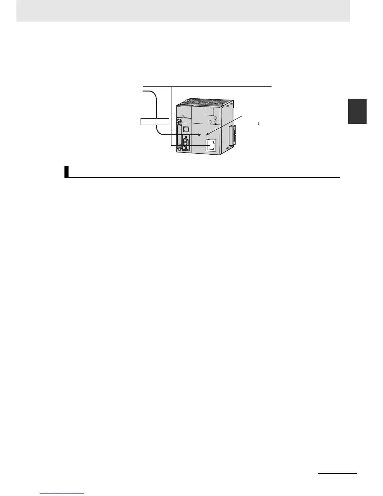
Tags are allocated in
a high-capacity area.
Designing is performed
by using only tags,
with no need to pay
attention to addresses.
EtherNet/IP
Specified by tag a.
CJ2 CPU Unit