3 Nomenclature and Functions
3-8
CJ2 CPU Unit Hardware User’s Manual
The MS and NS indicators can be green or red. The COMM, 100M, and 10M indicators are yellow.
These indicators can be lit, flashing, or not lit. The following table shows the meaning of these indi-
cator conditions.
Refer to SECTION 6 Troubleshooting for details on using these indicators for troubleshooting.
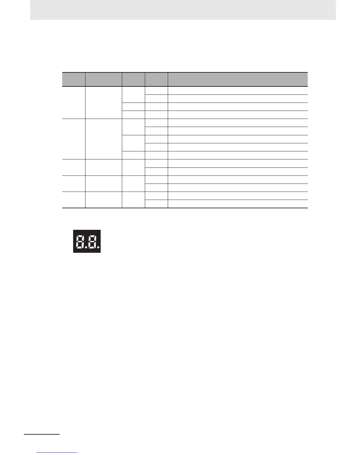
z Seven-segment Display
When the power supply to the PLC is turned ON or the CPU Unit is reset, all of the segments will
flash twice, and then the IP address set for the built-in EtherNet/IP port will be displayed on the 7-
segment display from right to left. After the entire IP address is displayed, the lower 8 bits of the IP
address (node address) will be displayed in hexadecimal.
Indica-
tor
Name Color Status Meaning
MS Module Status Red Lit Fatal error
Flashing Recoverable error
Green Lit Normal
--- Not lit Power supply OFF
NS Network Sta-
tus
Red Lit Fatal error
Flashing Recoverable error
Green Lit Tag data link and message connections established
Flashing Tag data link and message connections not established
--- Not lit Offline or power supply OFF
COMM Communica-
tion
Yellow Lit Transferring data
Not lit Not transferring data
100 M 100 Mbps Yellow Lit 100Base-TX link established
Not lit 100Base-TX link not established
10 M 10 Mbps Yellow Lit 10Base-TX link established
Not lit 10Base-TX link not established
EIP
21