78
Unit Components Section 2-2
b) Use the CS1W-CN114 when using the port as a peripheral port.
c) Use the CS1W-CN118 when using the port as a RS-232C port.
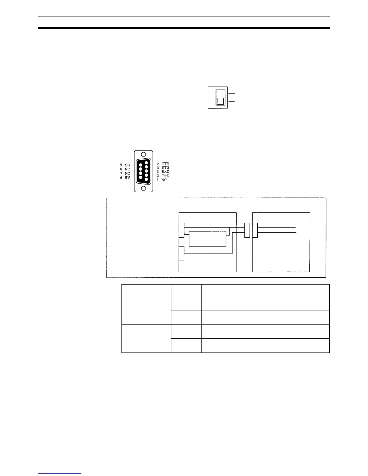
2. Cable Switch (SW1, CPM2C-CIF01-V1 Only)
Turn ON SW1 to use a CS1W-CN226/CN626 Connecting Cable to connect
to a personal computer. Turn OFF SW1 to use any other cable.
3. RS-232C Port
Used to connect to the RS-232C interface of a personal computer or Pro-
grammable Terminal (operator interface).
4. Connector
Connects to the communications port on the CPU Unit.
SW1
ON
OFF
Peripheral port on
CPM2C-CIF01-V1
Signal
conversion
Outputs signals from the CPU Unit’s CMOS inter-
face without conversion, or converts CMOS level
(CPU Unit side) to RS-232C (connected device
side).
Function Host Link, peripheral bus, no-protocol, or Program-
ming Console connections.
RS-232C port on
CPM2C-CIF01-V1
Signal
conversion
Outputs signals from the CPU Unit’s CMOS inter-
face without conversion.
Function Host Link, no-protocol, 1:1 Link, or 1:1 NT Link con-
nections.
Connector Pin Allocation
Internal Configuration
CPM2C-CIF01-V1
CPM2C CPU Unit
Peripheral port
(CMOS/RS-232C)
RS-232C port
(D-sub connector)
CMOS level
RS-232C conversion
Peripheral port
(CMOS level)
RS-232C port
(RS-232C)